This is a simple Arduino based solar charger that's hooked between my 30W mono-crystalline solar panel and a used-up 12V car battery. It was designed to sustain a maximum charging current of 2A and it can deliver up to 24W. I've made it in May and was supposed to be a temporary solution. Because it worked without a problem until September, I decided to write a post about it.
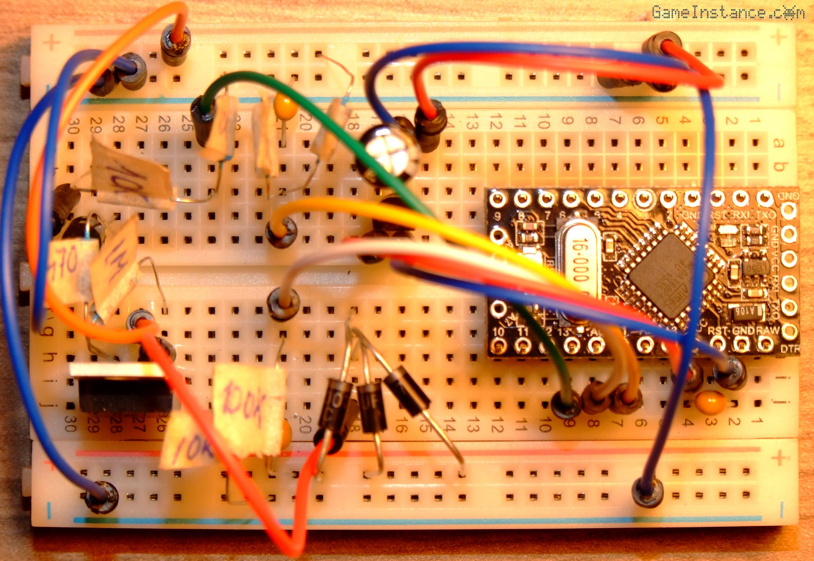 Breadboard prototype - ended up being used as is
If you're reading this, you may already know what the device is supposed to do. It charges the battery while keeping an eye on its parameters, chief among which is the battery voltage. Ideally, the charger should take into consideration the temperature of the battery, to measure the amount of energy delivered to or consumed from it and to estimate the current state of charge. It should be as efficient as possible and transfer all the power that the solar panel generates.
The circuit in discussion monitors only the battery voltage and doesn't draw the maximum power from the panel, hence its simplicity. The device is great if you have the solar panel, the battery but, for various reasons, no charger.
The circuit
is composed of an Arduino Pro Mini board, a P-Channel MOSFET, a smaller transistor and a couple of miscellaneous discrete parts. The sole purpose of the rig is to connect the panel to the battery when it's needed and disconnecting the two when it's not.
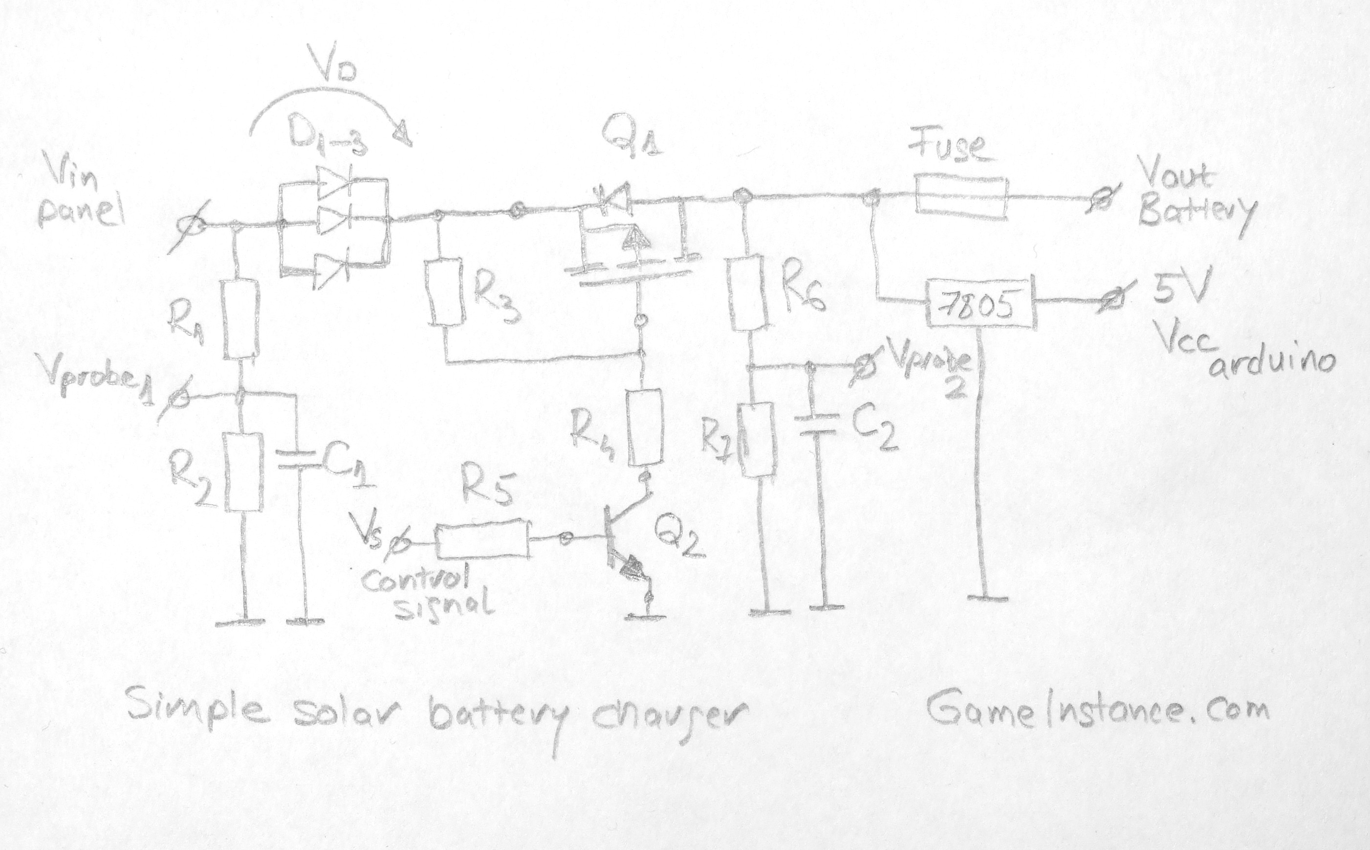 Solar battery charger schematics
BOM:
Arduino Pro Mini or a clone
Q1 - IRF4905 - P-Channel MOSFET with RDSon=20 mOhm
Q2 - 2N3904 - NPN transistor, IC=200 mA
D1-3 - UF4007 - IF=1 A, VF=1.7 V
R1 - 100 kOhm
R2 - 10 kOhm
R3 - 1 MOhm
R4 - 470 Ohm
R5 - 10 kOhm
R6 - 100 kOhm
R7 - 51 kOhm
C1,2 - 100nF
Fuse - 5 A
7805 - LM7805 - 5 V regulator
The R1, R2 and R6, R7 are forming two voltage dividers each reducing the voltage by different amounts for the Arduino's analog inputs. The first is used for probing the solar panel voltage while the second for the battery voltage. The C1 and C2 capacitors, although not really necessary, help keeping a steady voltage for the ADC to read and for the logic employed by the micro-controller.
The Q1 transistor does the switching job. Its low ON resistance introduces virtually no losses. The fact that it is a P-Channel simplifies the circuit because it can be controlled using a voltage that's lower than the one at the MOSFET source, which is readily available as the common ground point. The R4 and R3 are used for charging and discharging the MOSFET's gate. The Q2 is controlled by the Arduino logic output via the base current limiting R5 and opens a path for the current needed to charge the Q1's gate.
The D1-3 are three diodes with similar electric characteristic placed in parallel and in thermal contact with each other. I didn't have any higher current diodes at the time and decided to distribute the current given by the panel, around 1.7A, over more 1A diodes.
A little insight: The diode having the lowest forward voltage will heat-up the most as it'll pass through most of the current. Choosing them carefully with very close forward voltage and placing them in thermal contact yields an even current distribution. I try in general to keep the distributed current around half of the diode's rated value, hence three diodes. However, should a diode fail, it will fail open and that will overcharge to destruction the remaining diodes. Be wary, this trick is not generally accepted! That is why you should be using a 3A or bigger diode instead, if you have one.
The purpose of the diode(s) is dual. The first is to block the current flow from the battery into the panel. The second is to allow correct voltage measurements.
Last but not least, the 7805 regulator provides 5V for the Arduino VCC pin. The Vprobe1 connects to the A0, Vprobe2 to the A1 while Control Signal goes to digital port 13.
The logic
controlling the circuit is simple and can be split in two consecutive charging modes. The first connects the panel until the maximum battery voltage is reached, VMAX=14.4V. The second mode starts immediately after and tries to keep the battery at the float voltage, around VFLOAT=13.8V .
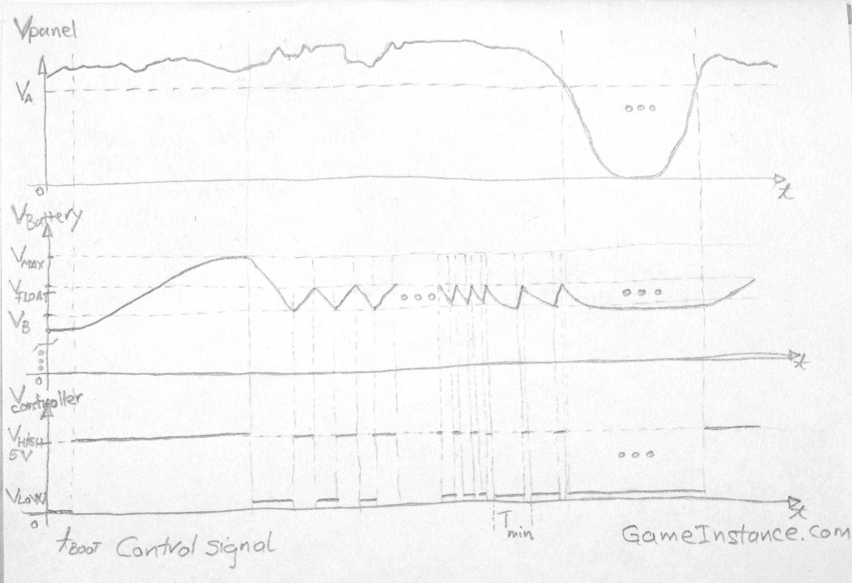 Charger's controlling signal
Check out: Switcharger on GitHub
So what happened in September?
Yes, I did mention it worked until then.
It stopped doing its thing one day and I had all components checked-out to discover that nothing was wrong. However, I found some melted plastic where the wire connecting the diodes and the power transistor entered the breadboard. I don't know what is the rated current for this breadboard or what not but one thing is certain: the breadboard wasn't made for more than prototyping. Seems that I'll have to build a PCB for it. Other than that, the circuit is a success.