With the advent of DAT in late 70s and CD in early 80s, digital recordings started gaining considerable ground. They evolved in parallel with their analog counterparts aiming to progressively replace them - vinyl being the rule-confirming exception. Of all mediums, CD remained popular for its robustness and generous 16bit 44.1kHz standard, even in today's terms. But, as with all things mechanical, not all of the 80s players aged well - as is the case for the massive SL-P10. Even the recent and more reliable ones won't remain in action forever and it's a darn shame they end-up gathering dust in an idle stack.
In an attempt to breathe new life back into my old compact-disk player, I'm creating a general purpose circuit based on a renowned DAC chip of the era, Burr Brown's PCM56, driven by a modern MCU and data source. This particular DAC features a carefully shaped NiCr R-2R resistor network yielding impressive THD for the K-rated chips, with the option to correct that value further more. The contained I/V operational amplifier eliminates the need for external components on the output stage, making it a modder's delight. Most of the top-shelf players of the 80s used it, the rest wish they had. It fell into oblivion with the MASH architectures that followed but remained a reference point.
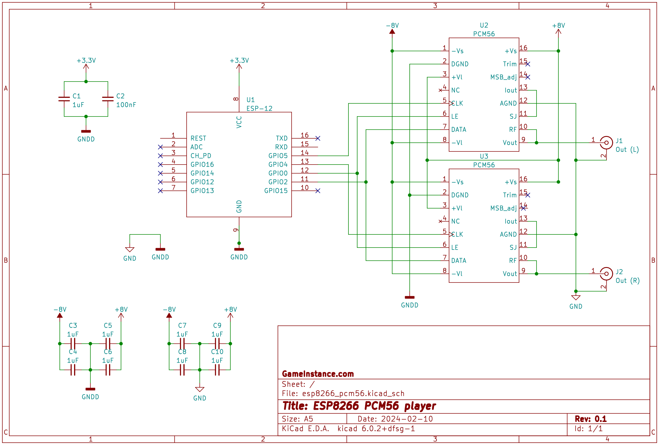
Of all design choices I'll go with the simplest: one MCU + two DACs. ESP8266 has enough high speed GPIOs, fast SPI interfaces and, above all, WiFi capability. PCM56's serial protocol predates the I2S readily available with ESP8266 but some custom bit-banging should solve that.
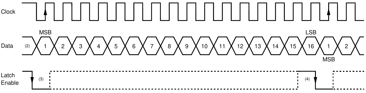 PCM56 signal timing chart for one sample
There will be one DAC per channel, sharing the DATA and LE (latch enable) lines, guaranteeing perfect phase alignment. Oversampling to at least 4x will push the switching noise further away from the audio spectrum, simplifying the circuit even more. However, to keep things simple, the sample rate interval will be kept 22 microseconds, roughly approximating the target 44.1 kHz.
Each channel in this test will play a different tone: 440Hz (tuning pitch) and 880Hz. An oscilloscope would show the two signals, perfectly aligned and with a roughly 3V amplitude, regardless of the rail voltage.
#include "gpio.h"


const int CLK1 =  5;
const int CLK2 =  4;
const int LE   =  0;
const int DATA =  2;

/* GPIO5 Macros */
#define GPIO5_MUX       PERIPHS_IO_MUX_GPIO5_U
#define GPIO5_CONF      PIN_FUNC_SELECT(GPIO5_MUX, FUNC_GPIO5)
#define GPIO5_OUTPUT_SET    do { GPIO5_CONF; GPIO_OUTPUT_SET(5, 0); } while(0)
#define GPIO5_INPUT_SET     do { GPIO5_CONF; GPIO_DIS_OUTPUT(5); } while(0)
#define GPIO5_INPUT_PULLUP_SET     do { GPIO5_INPUT_SET; PIN_PULLUP_EN(GPIO5_MUX); } while(0)
#define GPIO5_IN        (GPIO_INPUT_GET(5))
#define GPIO5_H         (GPIO_REG_WRITE(GPIO_OUT_W1TS_ADDRESS, BIT5))
#define GPIO5_L         (GPIO_REG_WRITE(GPIO_OUT_W1TC_ADDRESS, BIT5))
#define GPIO5(x)        ((x)?GPIO5_H:GPIO5_L)
#define CLK1_H          GPIO5_H
#define CLK1_L          GPIO5_L

/* GPIO04 Macros */
#define GPIO04_MUX      PERIPHS_IO_MUX_MTMS_U
#define GPIO04_CONF     PIN_FUNC_SELECT(GPIO04_MUX, FUNC_GPIO04)
#define GPIO04_OUTPUT_SET    do { GPIO04_CONF; GPIO_OUTPUT_SET(14, 0); } while(0)
#define GPIO04_INPUT_SET     do { GPIO04_CONF; GPIO_DIS_OUTPUT(14); } while(0)
#define GPIO04_INPUT_PULLUP_SET     do { GPIO04_INPUT_SET; PIN_PULLUP_EN(GPIO04_MUX); } while(0)
#define GPIO04_IN        (GPIO_INPUT_GET(14))
#define GPIO04_H         (GPIO_REG_WRITE(GPIO_OUT_W1TS_ADDRESS, BIT14))
#define GPIO04_L         (GPIO_REG_WRITE(GPIO_OUT_W1TC_ADDRESS, BIT14))
#define GPIO04(x)        ((x)?GPIO04_H:GPIO04_L)
#define CLK2_H           GPIO04_H
#define CLK2_L           GPIO04_L

/* GPIO0 Macros */
#define GPIO0_MUX      PERIPHS_IO_MUX_MTDI_U
#define GPIO0_CONF     PIN_FUNC_SELECT(GPIO0_MUX, FUNC_GPIO0)
#define GPIO0_OUTPUT_SET    do { GPIO0_CONF; GPIO_OUTPUT_SET(12, 0); } while(0)
#define GPIO0_INPUT_SET     do { GPIO0_CONF; GPIO_DIS_OUTPUT(12); } while(0)
#define GPIO0_INPUT_PULLUP_SET     do { GPIO0_INPUT_SET; PIN_PULLUP_EN(GPIO0_MUX); } while(0)
#define GPIO0_IN        (GPIO_INPUT_GET(12))
#define GPIO0_H         (GPIO_REG_WRITE(GPIO_OUT_W1TS_ADDRESS, BIT12))
#define GPIO0_L         (GPIO_REG_WRITE(GPIO_OUT_W1TC_ADDRESS, BIT12))
#define GPIO0(x)        ((x)?GPIO0_H:GPIO0_L)
#define LE_H             GPIO0_H
#define LE_L             GPIO0_L

/* GPIO02 Macros */
#define GPIO02_MUX      PERIPHS_IO_MUX_MTCK_U
#define GPIO02_CONF     PIN_FUNC_SELECT(GPIO02_MUX, FUNC_GPIO02)
#define GPIO02_OUTPUT_SET    do { GPIO02_CONF; GPIO_OUTPUT_SET(13, 0); } while(0)
#define GPIO02_INPUT_SET     do { GPIO02_CONF; GPIO_DIS_OUTPUT(13); } while(0)
#define GPIO02_INPUT_PULLUP_SET     do { GPIO02_INPUT_SET; PIN_PULLUP_EN(GPIO02_MUX); } while(0)
#define GPIO02_IN        (GPIO_INPUT_GET(13))
#define GPIO02_H         (GPIO_REG_WRITE(GPIO_OUT_W1TS_ADDRESS, BIT13))
#define GPIO02_L         (GPIO_REG_WRITE(GPIO_OUT_W1TC_ADDRESS, BIT13))
#define GPIO02(x)        ((x)?GPIO02_H:GPIO02_L)
#define DATA(x)          GPIO02(x)


const unsigned char sine_1t_440hz_raw[] = {
	0x00, 0x00, 0x6a, 0x06, 0xcf, 0x0c, 0x24, 0x13, 0x6a, 0x19, 0x92, 0x1f,
	0x9e, 0x25, 0x81, 0x2b, 0x3b, 0x31, 0xc2, 0x36, 0x13, 0x3c, 0x24, 0x41,
	0xfb, 0x45, 0x82, 0x4a, 0xc6, 0x4e, 0xb7, 0x52, 0x55, 0x56, 0x9e, 0x59,
	0x8b, 0x5c, 0x1a, 0x5f, 0x4d, 0x61, 0x1b, 0x63, 0x86, 0x64, 0x8f, 0x65,
	0x29, 0x66, 0x6a, 0x66, 0x36, 0x66, 0xa5, 0x65, 0xaa, 0x64, 0x49, 0x63,
	0x86, 0x61, 0x5f, 0x5f, 0xdd, 0x5c, 0xf2, 0x59, 0xbf, 0x56, 0x20, 0x53,
	0x3f, 0x4f, 0x02, 0x4b, 0x80, 0x46, 0xb6, 0x41, 0xaa, 0x3c, 0x5f, 0x37,
	0xdd, 0x31, 0x2d, 0x2c, 0x47, 0x26, 0x49, 0x20, 0x1a, 0x1a, 0xdf, 0x13,
	0x85, 0x0d, 0x27, 0x07, 0xb8, 0x00, 0x53, 0xfa, 0xea, 0xf3, 0x92, 0xed,
	0x4d, 0xe7, 0x1e, 0xe1, 0x11, 0xdb, 0x29, 0xd5, 0x66, 0xcf, 0xe0, 0xc9,
	0x82, 0xc4, 0x6d, 0xbf, 0x8f, 0xba, 0xfd, 0xb5, 0xb2, 0xb1, 0xb9, 0xad,
	0x0e, 0xaa, 0xbf, 0xa6, 0xc5, 0xa3, 0x2a, 0xa1, 0xf0, 0x9e, 0x13, 0x9d,
	0x9f, 0x9b, 0x8b, 0x9a, 0xe0, 0x99, 0x9b, 0x99, 0xbe, 0x99, 0x45, 0x9a,
	0x36, 0x9b, 0x88, 0x9c, 0x43, 0x9e, 0x5b, 0xa0, 0xda, 0xa2, 0xaf, 0xa5,
	0xe5, 0xa8, 0x6e, 0xac, 0x4e, 0xb0, 0x7f, 0xb4, 0xf7, 0xb8, 0xbd, 0xbd,
	0xc0, 0xc2, 0x04, 0xc8, 0x80, 0xcd, 0x2c, 0xd3, 0x08, 0xd9, 0x0c, 0xdf,
	0x2c, 0xe5, 0x70, 0xeb, 0xbb, 0xf1, 0x25, 0xf8, 0x88, 0xfe
};
const unsigned int sine_1t_440hz_raw_len = 202;

const unsigned char sine_2t_880hz_raw[] = {
	0x00, 0x00, 0xce, 0x0c, 0x69, 0x19, 0x9d, 0x25, 0x3b, 0x31, 0x12, 0x3c,
	0xf9, 0x45, 0xc4, 0x4e, 0x56, 0x56, 0x8b, 0x5c, 0x4b, 0x61, 0x89, 0x64,
	0x29, 0x66, 0x3d, 0x66, 0xa6, 0x64, 0x88, 0x61, 0xd8, 0x5c, 0xbc, 0x56,
	0x39, 0x4f, 0x84, 0x46, 0xa5, 0x3c, 0xe1, 0x31, 0x4a, 0x26, 0x1d, 0x1a,
	0x89, 0x0d, 0xb8, 0x00, 0xee, 0xf3, 0x4b, 0xe7, 0x11, 0xdb, 0x69, 0xcf,
	0x86, 0xc4, 0x90, 0xba, 0xb3, 0xb1, 0x10, 0xaa, 0xc4, 0xa3, 0xf2, 0x9e,
	0x9a, 0x9b, 0xe3, 0x99, 0xbb, 0x99, 0x36, 0x9b, 0x43, 0x9e, 0xd5, 0xa2,
	0xe6, 0xa8, 0x4d, 0xb0, 0xfa, 0xb8, 0xc1, 0xc2, 0x7e, 0xcd, 0x09, 0xd9,
	0x2d, 0xe5, 0xc1, 0xf1, 0x8a, 0xfe, 0x5b, 0x0b, 0x00, 0x18, 0x3e, 0x24,
	0xf4, 0x2f, 0xe1, 0x3a, 0xe7, 0x44, 0xd4, 0x4d, 0x8a, 0x55, 0xe9, 0x5b,
	0xd5, 0x60, 0x3d, 0x64, 0x11, 0x66, 0x4c, 0x66, 0xec, 0x64, 0xf4, 0x61,
	0x77, 0x5d, 0x7b, 0x57, 0x29, 0x50, 0x8b, 0x47, 0xd7, 0x3d, 0x20, 0x33,
	0xa7, 0x27, 0x84, 0x1b, 0xfa, 0x0e, 0x30, 0x02, 0x5f, 0xf5, 0xb7, 0xe8,
	0x6e, 0xdc, 0xb3, 0xd0, 0xb7, 0xc5, 0xa6, 0xbb, 0xa4, 0xb2, 0xde, 0xaa,
	0x69, 0xa4, 0x69, 0x9f, 0xea, 0x9b, 0xfe, 0x99, 0xac, 0x99, 0xf7, 0x9a,
	0xd2, 0x9d, 0x43, 0xa2, 0x1e, 0xa8, 0x6a, 0xaf, 0xe9, 0xb7, 0x9b, 0xc1,
	0x39, 0xcc, 0xb1, 0xd7, 0xc7, 0xe3, 0x4c, 0xf0, 0x17, 0xfd
};
const unsigned int sine_2t_880hz_raw_len = 202;


inline void set_ch1_sample_with_clock(int16_t &val) {
	for (int8_t i = 15; i >= 0; --i) {
		DATA(((val >> i) & 1) == 1);

		CLK1_H;  // CLK high
		CLK1_L;  // CLK low
	}
};

inline void set_ch2_sample_with_clock(int16_t &val) {
	for (int8_t i = 15; i >= 0; --i) {
		DATA(((val >> i) & 1) == 1);

		CLK2_H;  // CLK high
		CLK2_L;  // CLK low
	}
};

inline void set_samples_and_enable(int16_t &ch1_val, int16_t &ch2_val) {
	LE_H;  // LE enable

	set_ch1_sample_with_clock(ch1_val);
	set_ch2_sample_with_clock(ch2_val);

	LE_L;  // LE disable

	CLK1_H;  // CLK1 high
	CLK2_H;  // CLK2 high

	CLK1_L;  // CLK1 low
	CLK2_L;  // CLK2 low
};


union b2_i16_type {
	int16_t i;
	byte b[2];
};


auto val_ch1 = b2_i16_type{};
auto val_ch2 = b2_i16_type{};
auto i1 = uint16_t{0};
auto i2 = uint16_t{0};
auto t = uint64_t{0};

void setup() {
	gpio_init();

	pinMode(CLK1, OUTPUT);
	pinMode(CLK2, OUTPUT);
	pinMode(LE,   OUTPUT);
	pinMode(DATA, OUTPUT);
}

void loop() {
	if (micros() < t)
		return;
	t = micros() + 22;

	val_ch1.b[0] = sine_1t_440hz_raw[i1];
	val_ch1.b[1] = sine_1t_440hz_raw[i1 + 1];
	i1 += 2;
	if (i1 + 1 >= sine_1t_440hz_raw_len)
		i1 = 0;

	val_ch2.b[0] = sine_2t_880hz_raw[i2];
	val_ch2.b[1] = sine_2t_880hz_raw[i2 + 1];
	i2 += 2;
	if (i2 + 1 >= sine_2t_880hz_raw_len)
		i2 = 0;

	set_samples_and_enable(val_ch1.i, val_ch2.i);
}
The code above is a proof of concept and it is not to be taken for granted. It uses the Arduino setup/loop API, functions have been inlined to avoid awkward memory placing attributes and no timer interrupts were used. Above all, no cooperative multitasking efforts are made and ESP8266's watchdog periodically restarts the MCU for starving internal tasks of execution. Some will also observe the use of union type punning, others will argue the GPIO toggling macros. Something about the timing hack... anyone?!
Ignoring the above-mentioned, we get a functional system capable of playing a 16bit signed PCM at 44.1 kHz. Even with temporary breadboard connections and switching-mode power supply on the rails, the PCM56 sounds clean, promising, and I cannot wait the next step: have it play raw PCM data from an external source.