As countries prepare for gradual FM/AM phase-out, the price for analog radio receivers will drop to a specific minimum representing either their price per (aged) parts, raw materials or any historic value they may represent. The ST-S707 will likely fall into the latter for being among the first digital synthesizer receivers featuring advanced signal processing but also for having interface traits that remained in use for the decade that followed. Since I'm a sucker for old Technics gear, I had to salvage one from inevitability, or so I keep telling myself.
This article treats its disassembly, cleanup, investigation and some minor repairs.
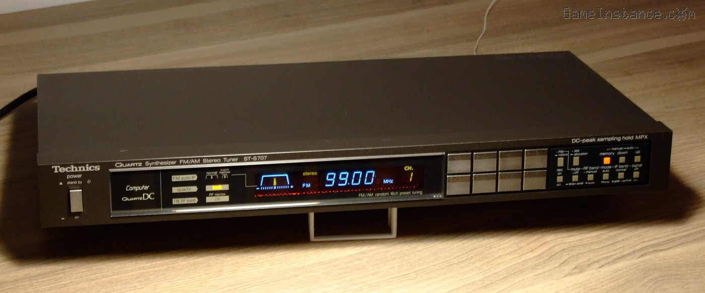 Technics ST-S707 - black
Whoever had it before, took good care of it. It had mild abrasions, minor greasy dirt around some buttons but overall, it was in good shape considering it being 40 years old. However, I noticed the channel settings were lost after leaving it unplugged it over night. Unsurprisingly, this was caused by the super-capacitors that hold the settings in memory. Much like the CR2032 battery holding PC BIOS configurations and RTC, a pair of 3.3 farad capacitors insure the necessary voltage for long off-line periods and, just like any battery, they're subject to aging too.
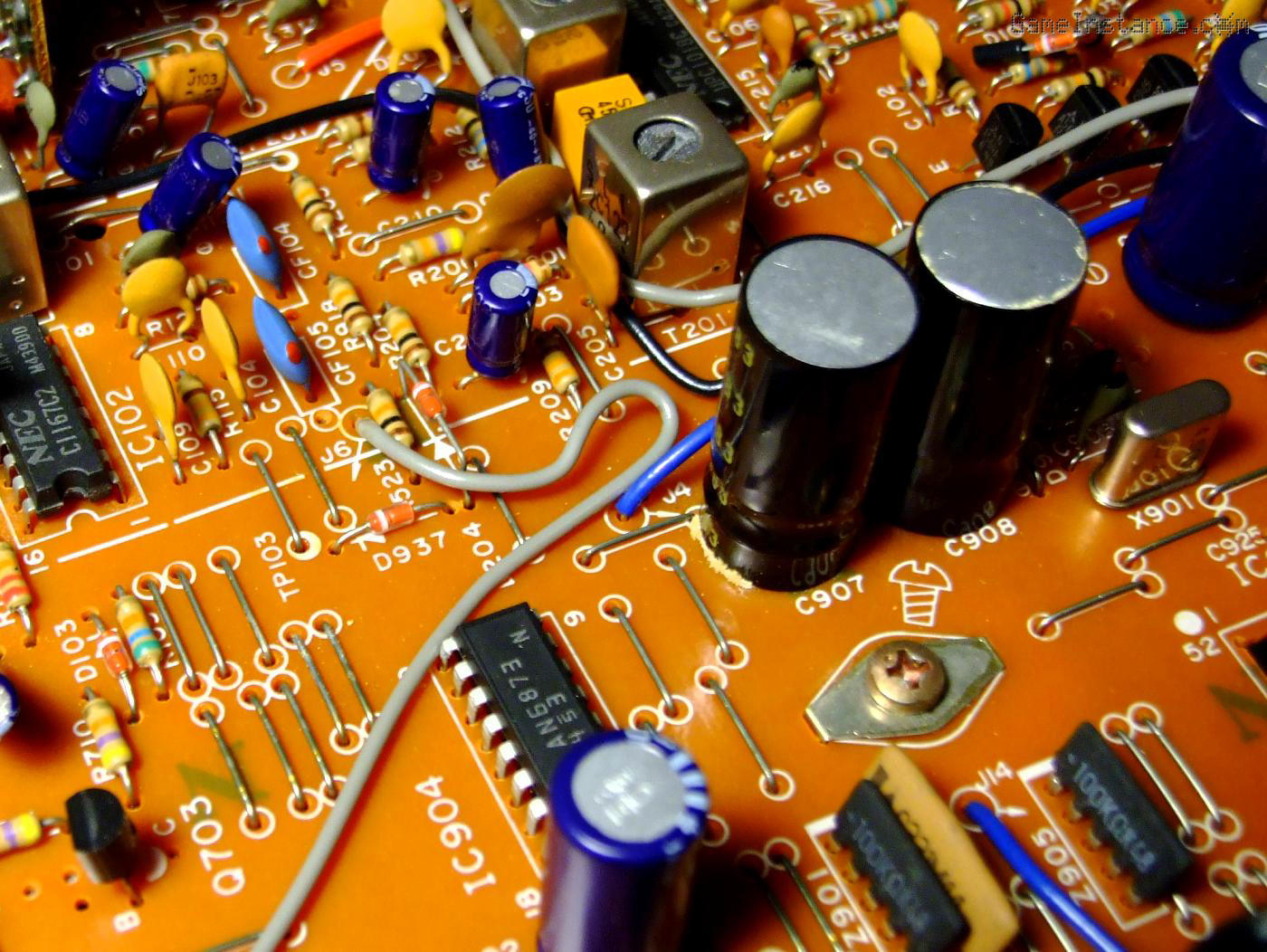 Technics ST-S707 - C907-908 memory holding super-capacitor series
To make matters worse, they're connected in series to provide the operational voltage for the memory chip. With time, capacity or ESR drift cause charge imbalances that make one of the capacitors to go above the rated maximum, leading to its failure. Unfortunately, the constructor chose to have one Zener diode to limit the series total voltage and chose to ignore this phenomenon.
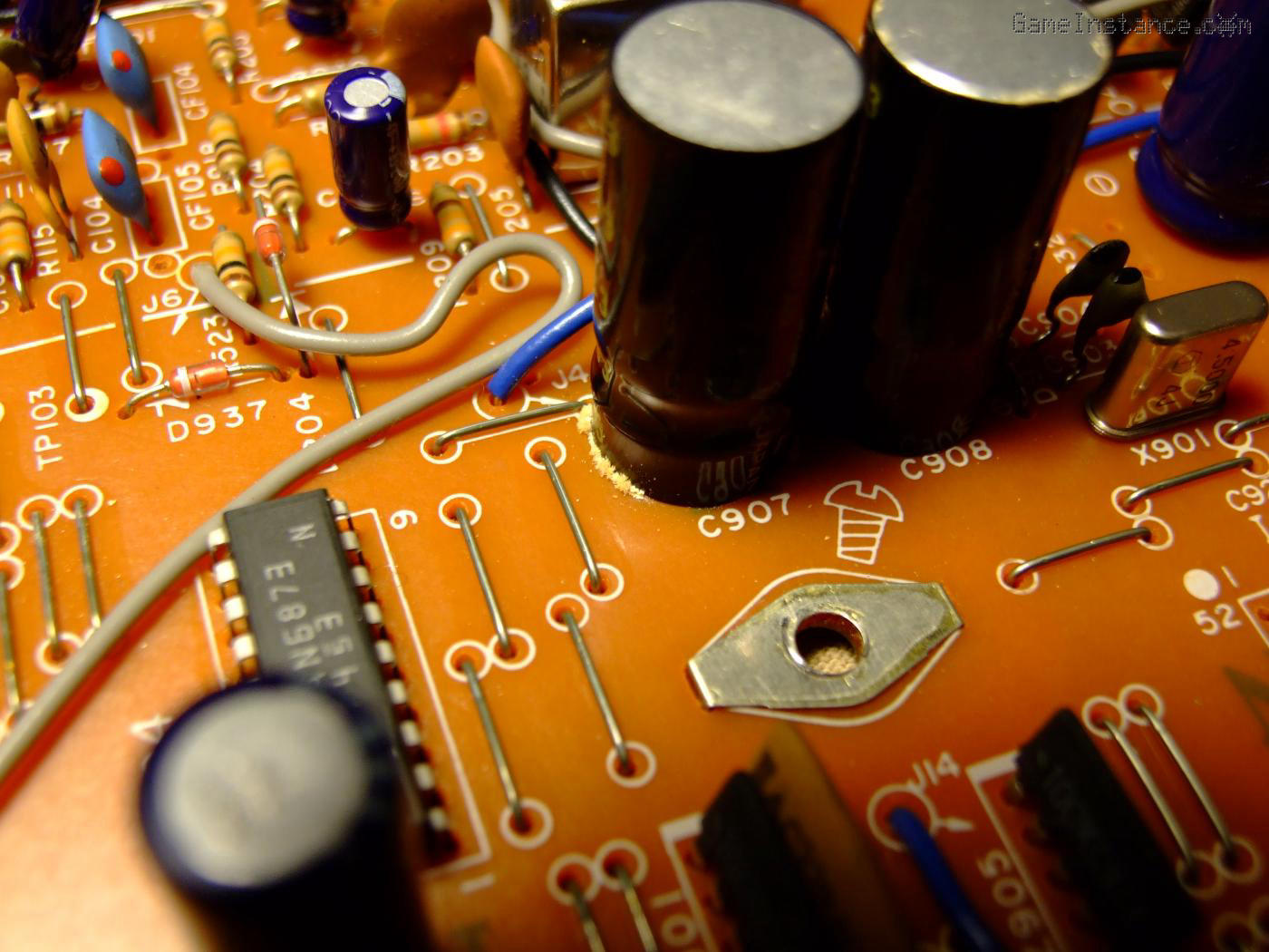 Technics ST-S707 - C907 dried-up super-capacitor
The one that failed was closest to the power supply section of the board but I'll get back to that in a second. The PCB pad below the leaked capacitor was completely etched (copper, tin plating and solder, all gone) making me wonder about the chemical composition of their dielectric.
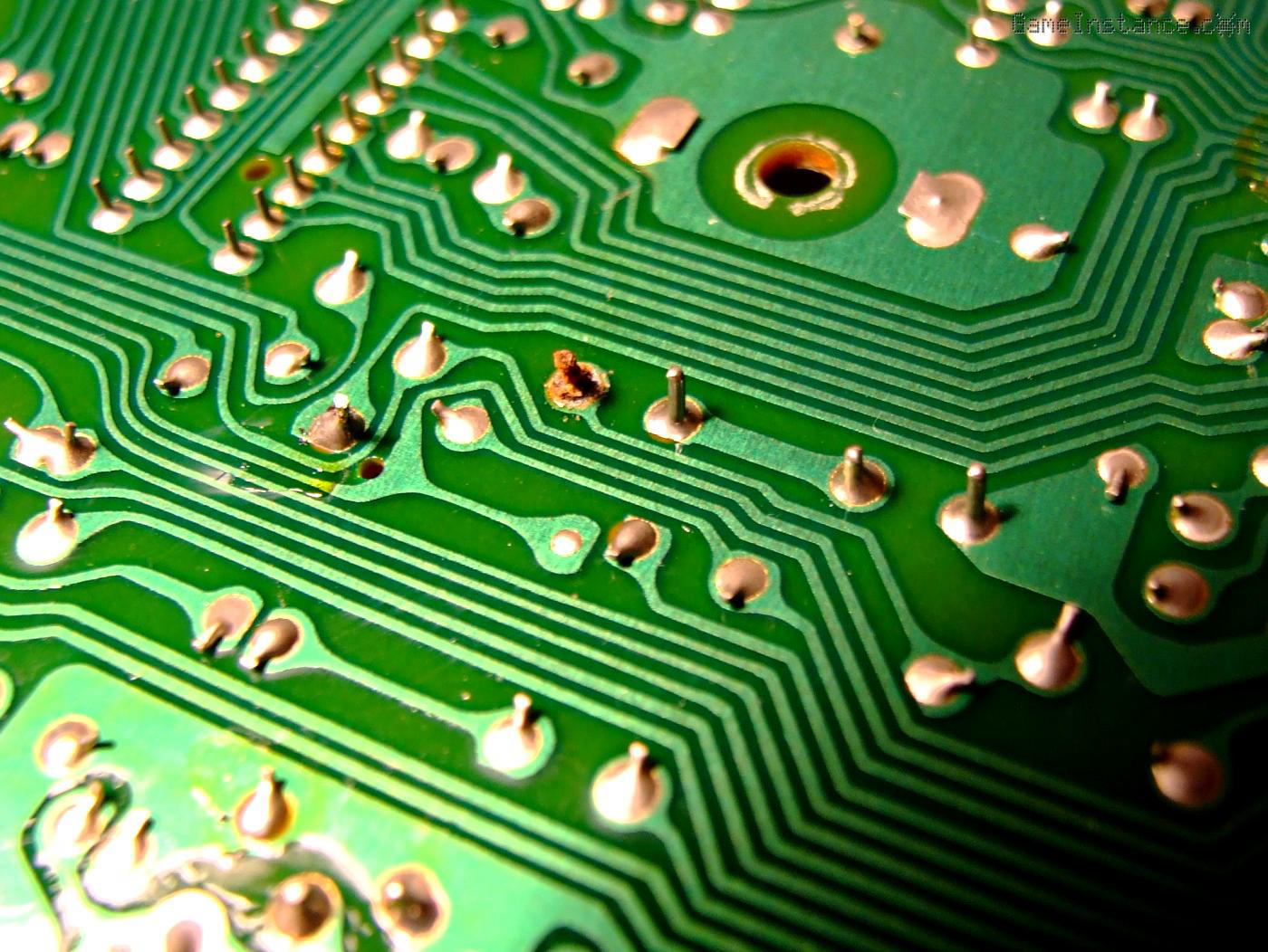 Technics ST-S707 - C907 super-capacitor etched pad
The bad capacitor was holding no charge while the other still had 0.7 V. The PCB was so damaged that there was no electrical contact between the pad and the pin. Weirdly, the tuner was still able to hold the memory for few hours. Later I found that the chip's low power requirements made the filtering capacitor act as an intermediary supply.
Very carefully, I de-soldered the capacitor touching one pin at a time. The good capacitor had enough energy to cause a powerful spark. Yes, I did discharge it with a power 5.6 Ohm resistor beforehand but still. The pad needed some restoration before installing the new caps, but that too was a quick fix.
For the same footprint, the replacement capacitors were bigger: 6 Farad. I chose them knowing that's not going to be a problem as long as the current limiting resistor can put up with a short across the pins of the deeply discharged capacitors.
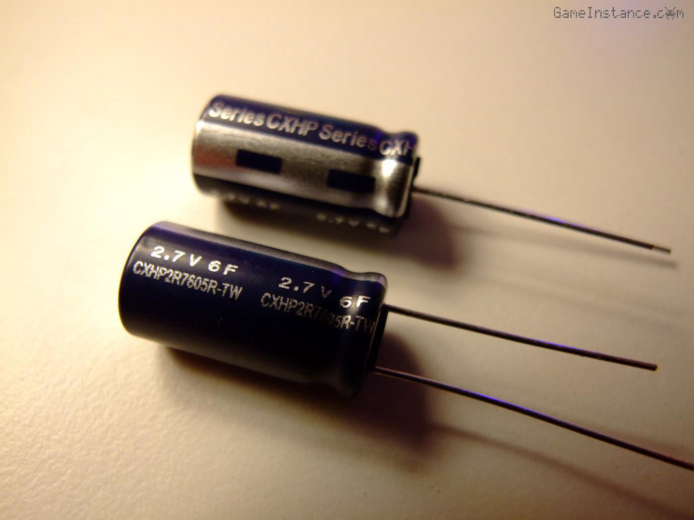 New super-capacitors, bigger that the original
For the above series considerations, I took some time to balance the charge level in the new capacitors. They came with 230mV and 300mV so I used the same resistor to discharge the second to roughly the same voltage as the first. This insures none will surpass the maximum rated 2.7V. Of course, I could have modified the design to replace the series 5V zener with one 2.5V per capacitor. That technical choice was OK for decades. Why change it now?
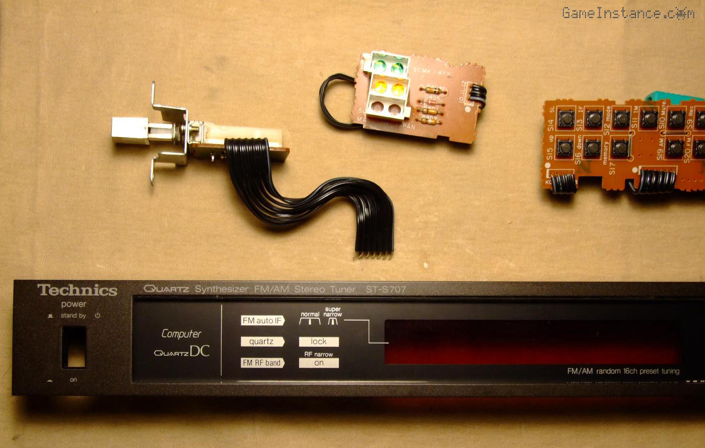 Technics ST-S707 - Front panel disassembly for inspection and cleanup
Cleanup followed but there's nothing interesting there. Plastic behaved well, screen was slightly scratched already so I went easy with it. The bottom metal frame of the case had a rust spot just under the leaky super-capacitor but nothing bad.
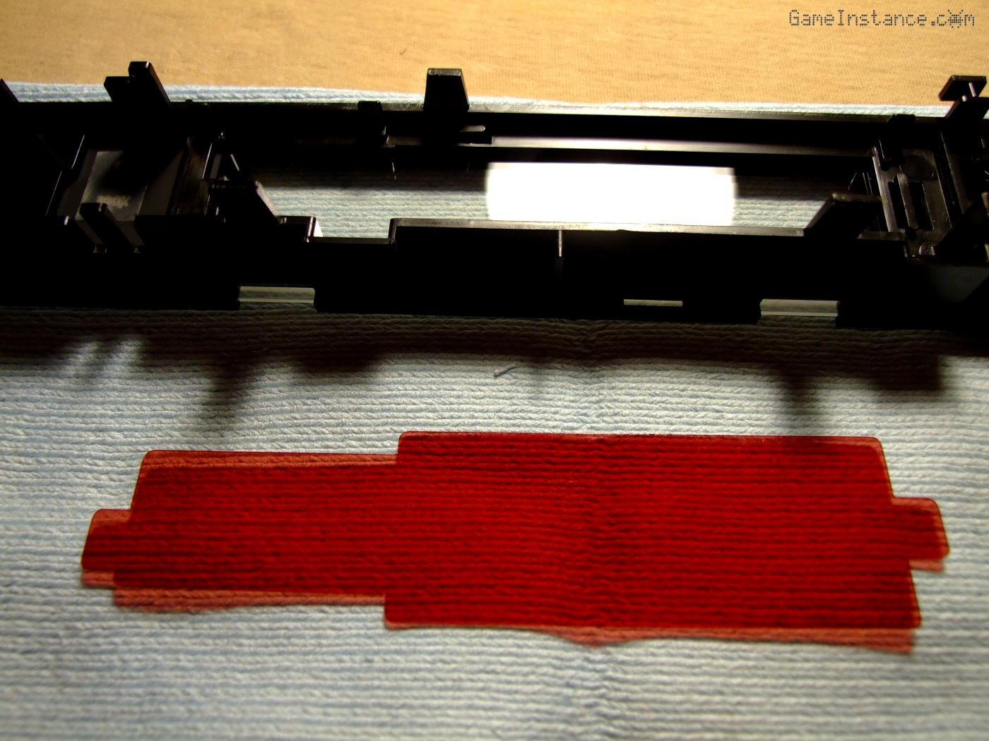 Technics ST-S707 - Fluorescent screen filter
The fluorescent display filtering screen was handled carefully as well as it was prone to abrasions and electrostatic. Power button squeakiness got away with some good old WD-40. With all in order, I continued with the reassembly.
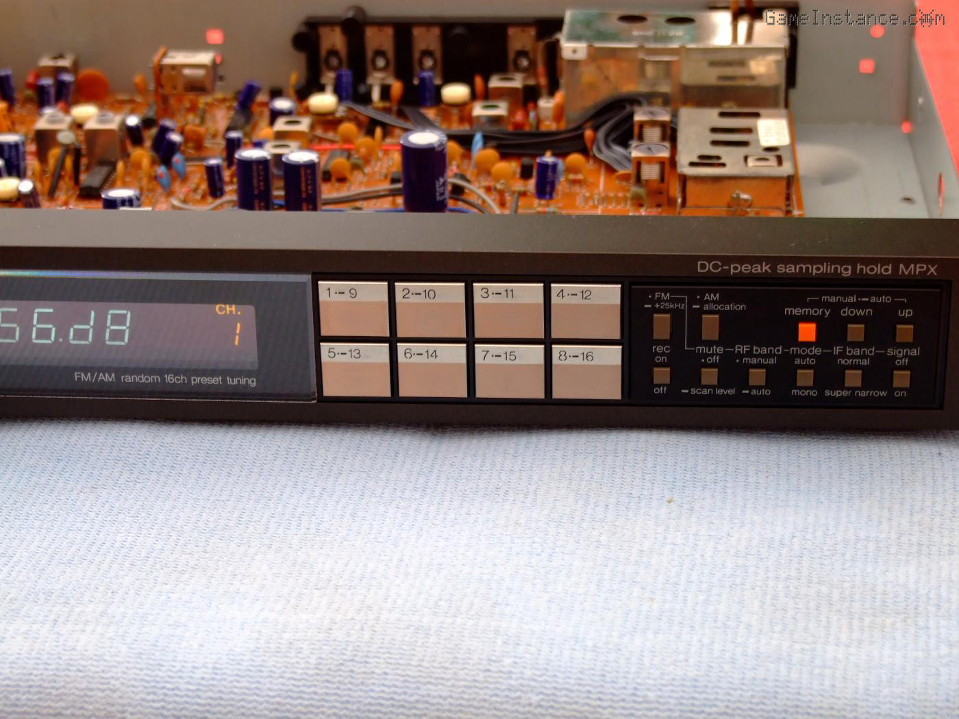 Technics ST-S707 - Cleaned-up and partially reassembled
One thing I noticed was the darker tint of the PCB around the voltage regulators of the power supply. The one insuring the 14.7V is pretty warm all the time. It was a deliberate choice of the constructor to sink heat via one TO-220 transistor package and the nearby board traces. I was considering a heat-sink add-on but the proximity to other parts made that difficult. That said, the regulator circuit features two more resistors in series, upstream of the regulator. Slightly more elevated from the board level, they're taking some of the dissipation burden from the transistor.
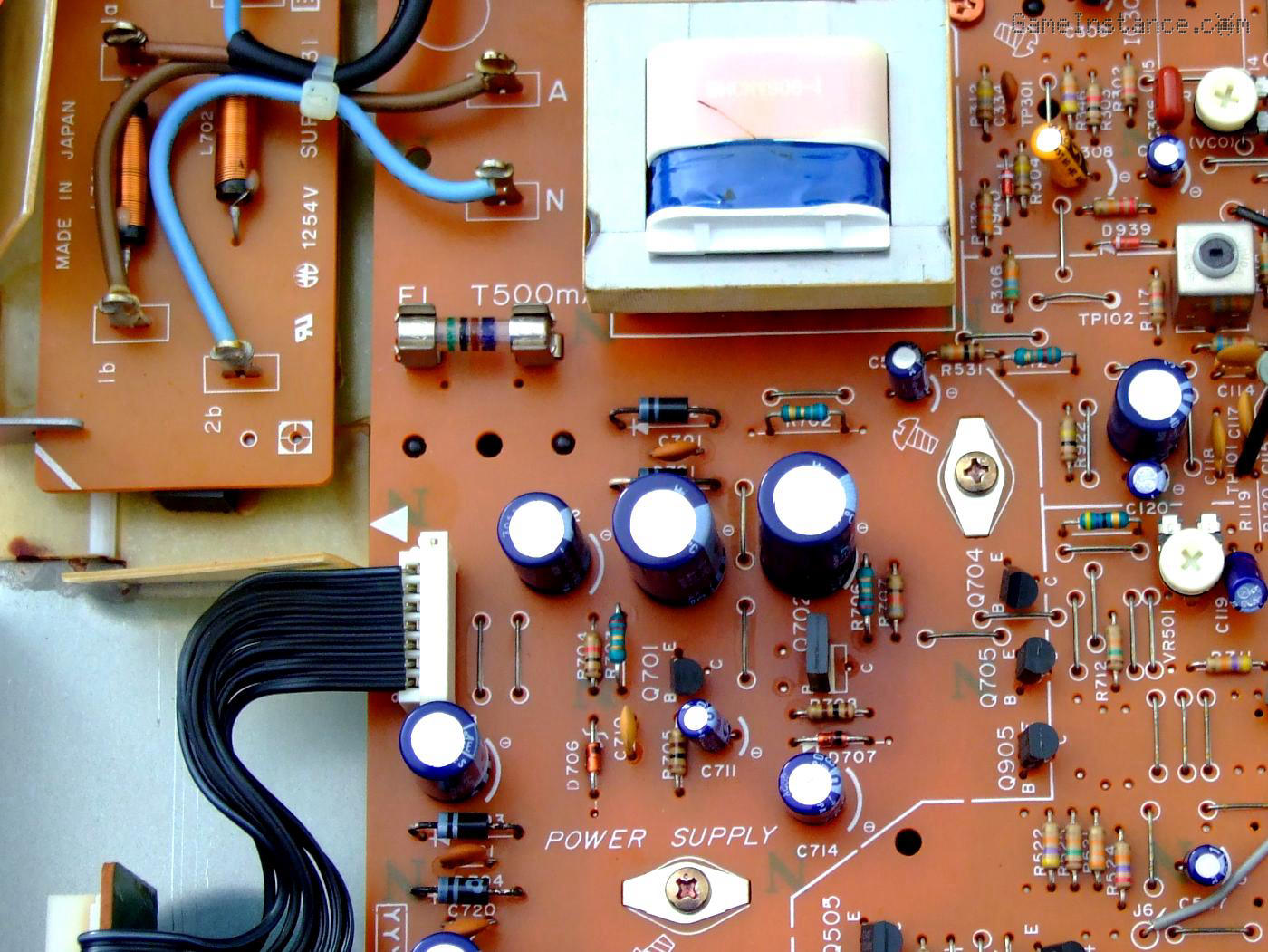 Technics ST-S707 - Heat affected PCB around power supply
The unit was designed to be always on even when turned off. As a consequence, the transformer had to perform for months on end without overheating. To transfer some of that heat outside the chassis, a black foamy pad connects it thermally with the top case. This was a deliberate technical choice to maintain super-capacitor's charge level, long before Energy Star and other standards came into action. Needless to say, it draws just shy of 10W, so that's not a huge waste.
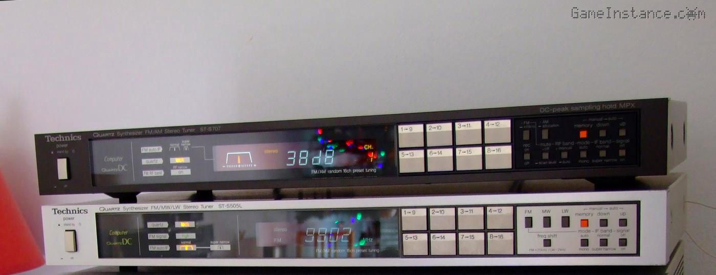 Technics ST-S707 stacked on top of an ST-S505L, of the same era
Both ST-S707 and the ST-S505 were very good tuners of the early 80s. While the latter was an under-priced over-achiever, the former was state of the art as it featured the famous DC peak sampling hold MPX circuitry, which further improved channel separation. I didn't re-align any of them and still perform in specs. Both were designed and built in Japan and, leaving aside the minor flaws these and other subsequent models had, the fact that they work even today is a quality statement.