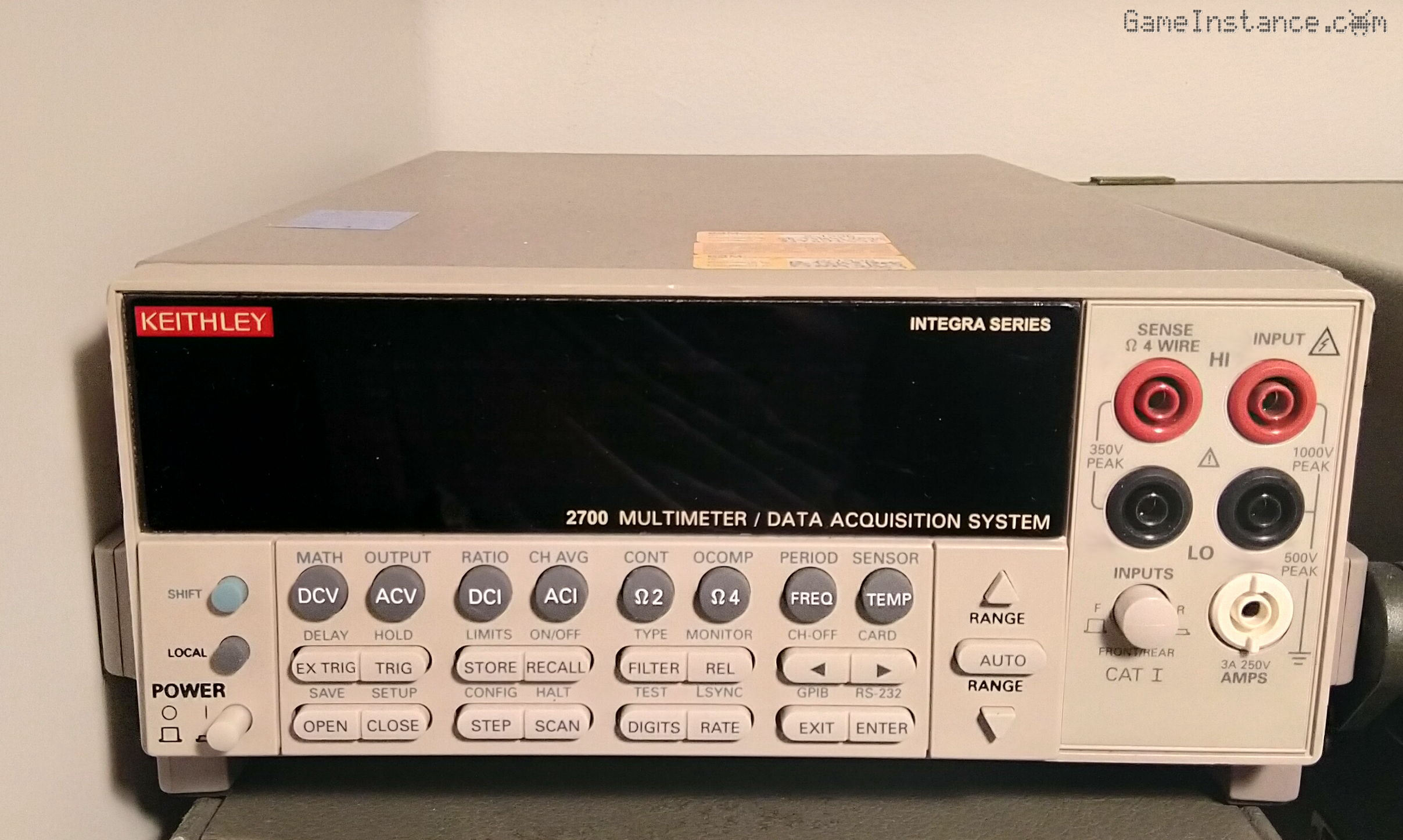
Sometimes, a deal is too tempting to pass up. Few days ago I spotted a Keithley 2700 with a 7700 multiplexing card advertised at a compelling price, but having a major flaw: a No Comm Link error preventing measurements. The service manual hinted at a potentially difficult repair, but I felt confident - based on the ad photos, description and manufacturer documentation - that this unit wasn't beyond saving. It was a calculated risk, and one I was willing to take.
The reward? A high-performance DMM for my lab, resurrected from the brink.
Upon arrival
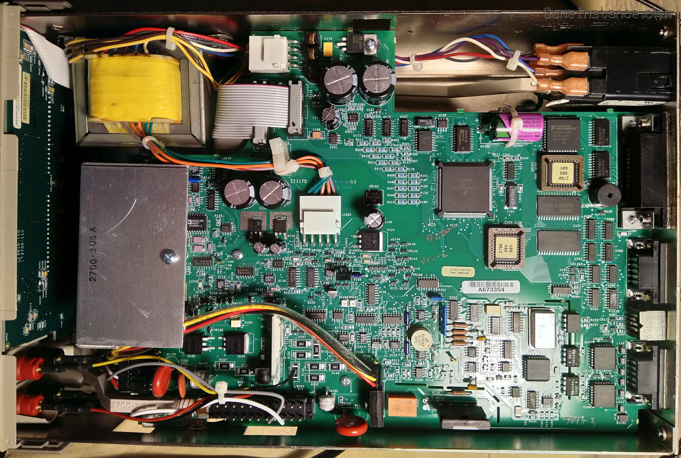
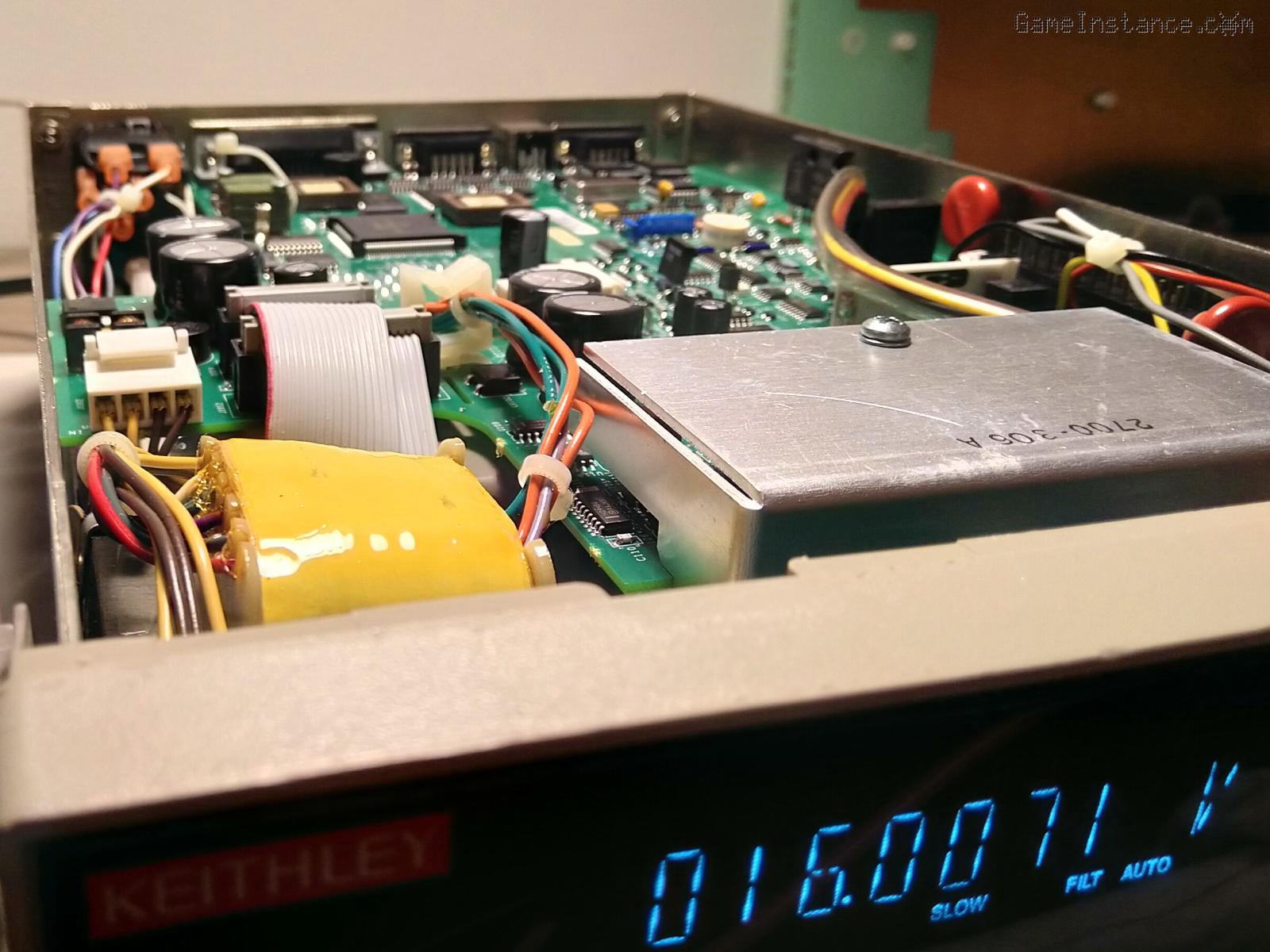
It had visible traces of use, few melted spots on the front - likely from a repair shop or a lab dealing with hot items, the usual greasy dirt layer and several calibration stickers, last one pretty recent, dated 2021. As always, I took the lid off for a quick electric sanity check and popped-out the 7700 card from the back. It was spotless on the inside, not even a speck of dust, unlike the Fluke 8840A I got earlier this year. The main board and parts were OK, capacitors, diodes, regulators, none presenting obvious issues.
Primary battery
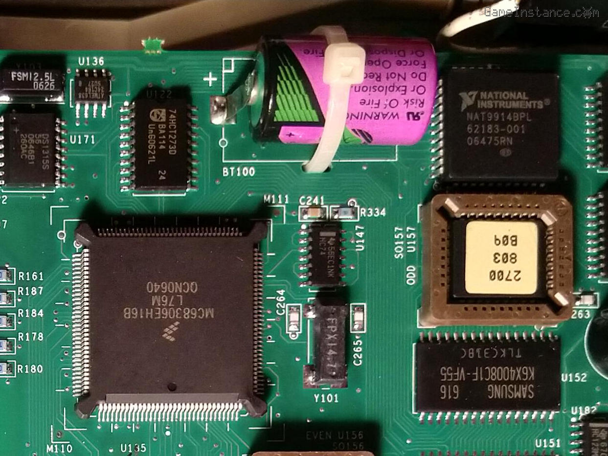
Unsurprisingly, the DMM had a 950mAh 3.6V lithium battery for the purpose of keeping the RTC and some CMOS configuration in the NVRAM memory. It was now measuring 0.6V, which meant those settings were long gone. The service manual schematics refers to it as BT100, with a BA-51 Keithley part code. The cell is labeled Tadiran, has PCB-mounting terminals and a rather exotic 1/2 AA format, specific to US-made devices.
Power test
I found a bit off the 220V AC grid setting on the back panel fuse compartment. For context, the unit has 4 options: 110, 120, 220 and 240. In most EU countries 240V AC is the norm, so I corrected that. On first power-up the "No Comm Link" showed and nothing else happened, although few seconds later a low sizzling noise gradually appeared, originating from the central side of the board. Gently tapping parts changed nothing in terms of noise. Nothing seemed to heat-up excessively after several minutes of operation so I power cycled the device.
Once rebooted, the failure message disappeared, the machine beeped (pretty loud), displayed a revision number, some unknown values, an error code +520 and then resumed normal operation. Whatever happened to it, it wasn't catastrophic. It was displaying DC volts, I was able to make selections, change ranges and setting. To my absolute surprise, it was working! Several quick reboots didn't throw the unit back into the unrecoverable failure mode. This made me think the problem was manifesting on cold starts, which was confirmed.
Power rails
Measuring the voltages on the power rails revealed nothing out of the ordinary, all values being within specs. The regulated +/-15V DC rails measured +/-14.8V, perfectly normal. On the unregulated side, only the positive one had a 0.6V, 100Hz ripple, with no effect on the regulated voltage.
The digital +5V DC and +37V DC were within the +/-5% specs as well, with a rather high 1.8Vpp ripple on the regulated +37V rail. Judging by the value, the latter provides the cathode-annode potential of the vacuum fluorescent display and so that ripple magnitude won't affect its performance. The C104 capacitor, filtering said voltage, is going bad and probably the source of the noise but nothing critical.
The analog +/-15.7V DC rails were measuring +/-15.79V and the +5V DC had a steady 5.029V. No ripple whatsoever on neither of these, which meant the operational circuitry was powered correctly and no short-circuit is present.
Conclusions
Although not critical, the 220V AC line voltage selection instead of the actual 240V AC, pushed the filtering capacitors closer to their maximum rated voltages and made them run warmer, which means they have aged faster than they should have. Likely that's the cause of the noisy +37V capacitor. Regulators can run hotter too but some, if not all, have built-in over-temperature protection, making them less prone to failure. If the power supply would have relied on a SMPS, this wouldn't have happened. Unfortunately, and for some very solid reasons, the supply uses a multi-tap, multiple secondary transformer which makes line voltage selection quite important.
The depleted BT100 battery suggests that the unit most likely was shelved or unused lately. Its very low voltage led to configuration memory data corruption, which in turn caused miscommunication between the modules. The service manual suggests one such miscommunication on the main board could be the root of the "No Comm Link" message. This theory was later confirmed, as feeding an external 3.6V supply onto the terminals of the removed battery led to normal operation on every boot, even on cold starts.
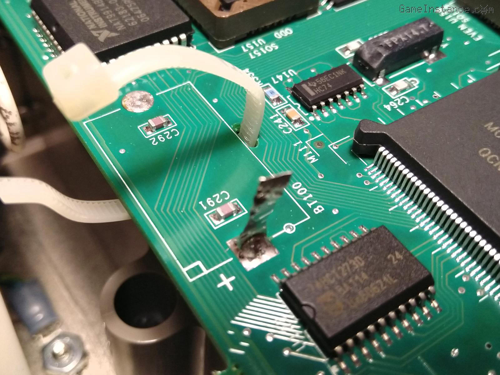
Although I could have purchased a 1/2 AA battery with PCB terminals and replaced it directly on the board, I chose to 3D print a 2032 socket which would then be mounted on the PCB. This decision was made based on 3 factors, the most important being that any future battery replacement would no longer imply PCB soldering. In case you never read the service manual for one such DMM, it's quite an endeavor. The board needs to be treated with utmost care when soldering: using organic activated flux, then thoroughly washed with pure water, then with methanol and, at the end, dried for several hours at 50 degrees Celsius. Not to mention the risk of operating with static sensitive CMOS devices. Second, 2032 lithium batteries now have capacities similar to the original and lastly, 2032 batteries are commodity products, commercialized in virtually every store; that's not the case for the 1/2 AA cells, especially those with PCB mount terminals.
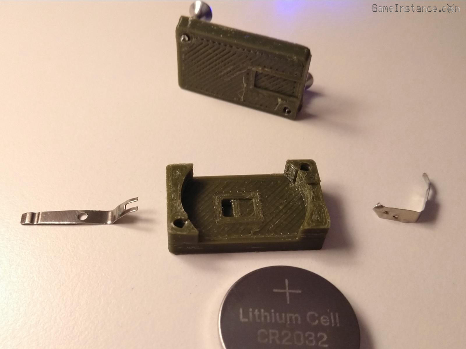
The only down-side of this was that none of the open 2032 socket models available online were matching the old 1/2 AA footprint. Some 30 minutes later I had my own OpenSCAD designed model which I 3D printed and mounted on the board. One annoying issue with 2032 mounts is the imperfect contact with the battery. Often times one encounters "low battery" behavior even though it is still good. That's the main reason I chose a two piece, screw-in mount, such that I can control the terminal pressure on the battery.
I re-assembled it and played with my new, very precise measurement device. It is now the most expensive and accurate piece of equipment I have in my amateur lab. I haven't replaced any caps yet, on the principle that "if it ain't broke..." and because this unit was manufactured in 2014, so it should still be OK for a number of years. Also, I'm planning on checking the 2032 battery voltage again in 6-12 months and decide then if a capacitor replacement is necessary.
Quick overview
Bringing this Keithley 2700 back to life has been a satisfying project and it serves as a reminder that even complex instruments can be rescued with a little patience and a methodical approach. If you're considering a similar repair, the service manual is invaluable, though be prepared for a detailed process. Don't underestimate the impact of seemingly minor issues like a depleted battery - they can manifest in unexpected ways.
While my unit would benefit from a formal calibration, initial measurements closely align with those from my Fluke 8840A, suggesting acceptable accuracy. Now, the real fun begins - putting it to work and exploring its full potential. I'm particularly interested in exploring its data acquisition capabilities with the 7700 card and automating some of the more repetitive measurements.
On the subject of automation, there's a Python library available on GitHub for this DMM, making quick prototyping possible. Moreover, the user manual contains a comprehensive API description, allowing implementation in other programming languages as well.