In many ways similar to the Astable Multivibrator, the following circuit has an even more useful function: memory. Instead of alternating pulses at a specific period, this one stores a certain state as long as it has power. It's called bistable multivibrator but it also goes by flip-flop and latch.
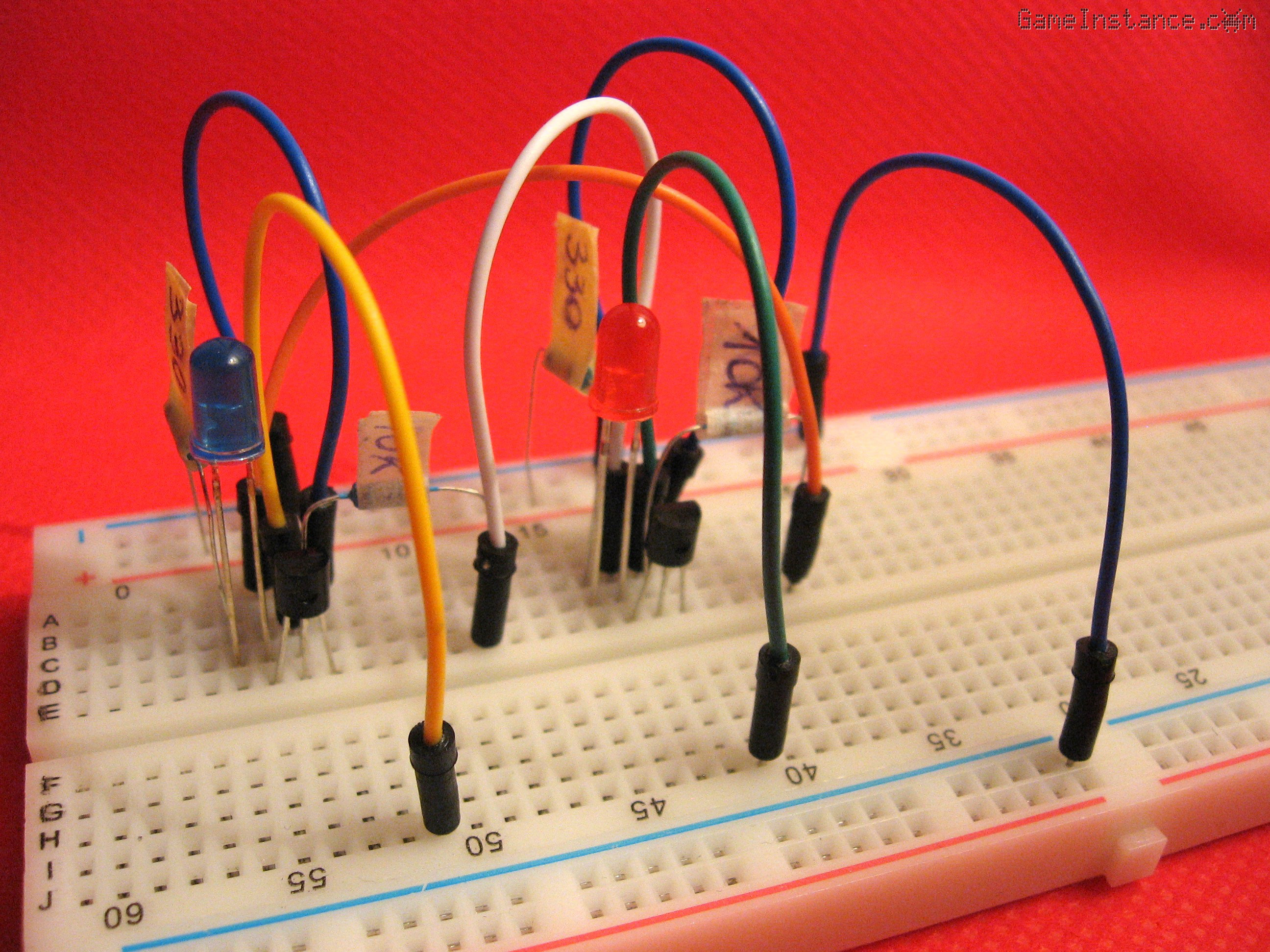 Flip-flop memory - breadboard setup
The flip-flop
is composed of two transistor inverting amplifiers backs to one another. The negative reaction of one amplifier is fed into the other and vice-versa. When one transistor opens, its output pulls the base of the other transistor way down, closing it. Pressing any of the buttons will open the corresponding transistor and close the other one. That state will be preserved after the button was pressed, hence the memory function.
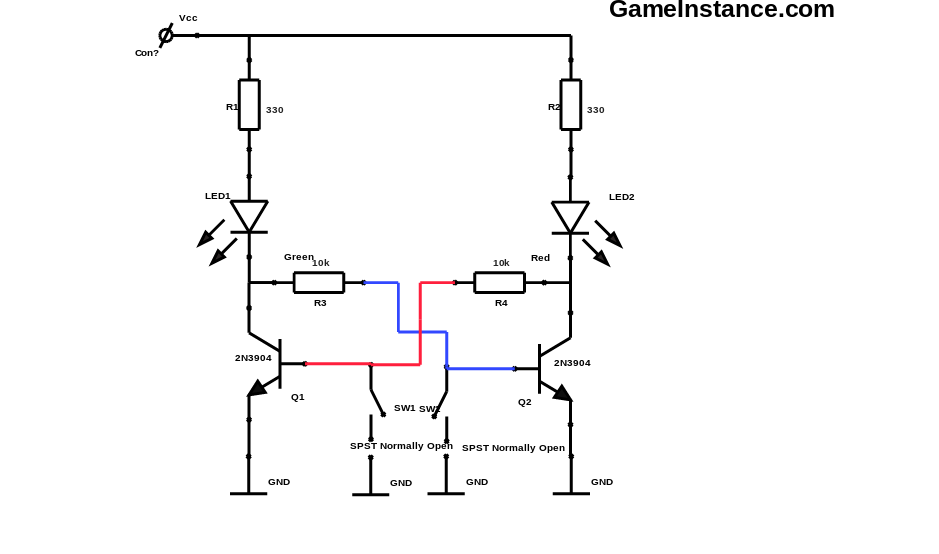 Flip-flop schematics - LEDs indicating the state
Bill Of Materials:
Q1, 2 - 2x 2N3904 NPN bipolar transistor
LED1, 2 - Green and Red LEDs
R1, 2 - 330 Ohm
R3, 4 - 10 kOhm
SW1, 2 - 2x Normally Open switches
Breadboard
Jumper Wires
Although the state differences are obvious, one LED being brighter than the other, the OFF state LED is still lit. Why? Well, because of the small current flowing through the base of the opened transistor. If we take a closer look at the 2N3904's data sheet we see that for a 10 mA collector current the base current at saturation is 1 mA. That small amount is enough for a reduced scale electroluminescence to take place.
There's a downside
to any real-life device and this one's is asynchronism. The circuit has two inputs that need to be put to GND alternatively to store either a HIGH or a LOW and that is useless for any modern computer. What's missing is a clock line and an input that accepts both HIGH and LOW levels but that's a different story.