Another sequel. I know, I cannot help it. In the ending of my last sensors post I've briefly enumerated some of the popular Hall effect applications. One function worth mentioning and that I plan on using in my future projects is the current sensing.
Among many, there's the ACS712 chip which is produced by Allegro in three flavors, each with a current limit of 5, 20 and 30 amps. The circuit gained its popularity with the advent of breakout boards for Arduino and abunds on all specialized marketplaces.
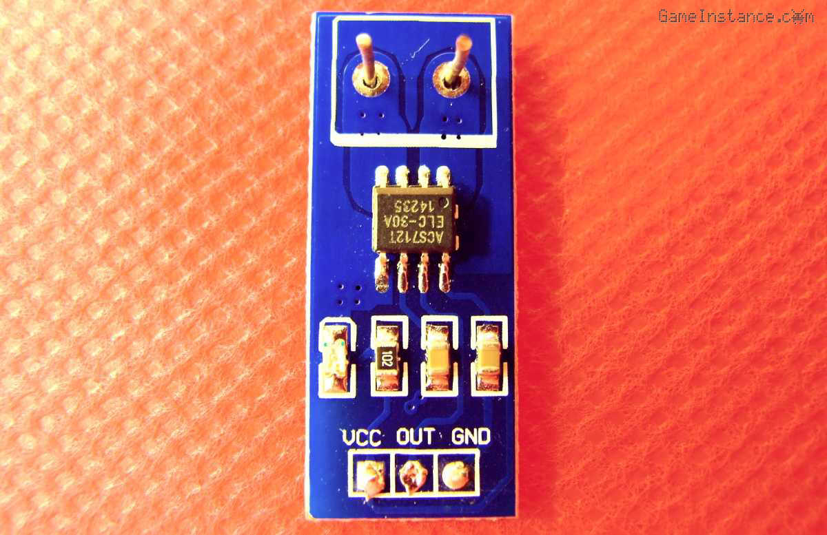 Allegro ACS712 30A current sensing chip mounted on a breakout board
Function
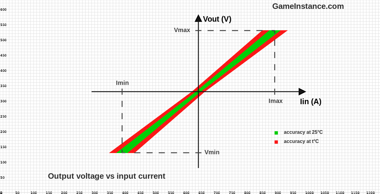
The sensing device has a low impedance path for the measured current - the input - and a pin that varies its output voltage proportionally with the measured current - the output. The relation between the output voltage and the input current gives the sensitivity which is expressed in V/A or mV/A. Then there's the accuracy of the circuit that indicates the maximum deviation from the specified ideal line given by sensitivity.
With no input current, 0A, the circuit outputs half the Vcc value. For every input amp the output voltage increases with the sensitivity value. For ACS712-30A that means 66mV per ampere.
Perks
The Allegro IC features a patented technique called Chopper stabilization aiming at the minimization of the parasitic offset and thermal drift that are specific to high gain amplifiers. In itself, the concept isn't new. It has been around since the late 40s for operational amplifiers, serving the same purpose of minimizing output drift. It differs by the fact that it sources two orthogonal and differential signals from the Hall effect plate and feds them alternatively to the input of a differential amplifier through the said chopping. That's called dynamic offset cancellation and it is meant to reduce the residual offset. The useful information is then extracted from the amplified signal by rejecting the high frequency components. In theory, that should be a great improvement and the datasheet confirms it.
Test rig
This isn't the simplest setup. For that you should replace the Arduino with a voltmeter set on a scale of minimum 5 volts. This involves the Arduino solely because that's how the chip is used. The voltmeter measurement would have a real purpose only if your voltmeter is a standalone tool, with no ammeter.
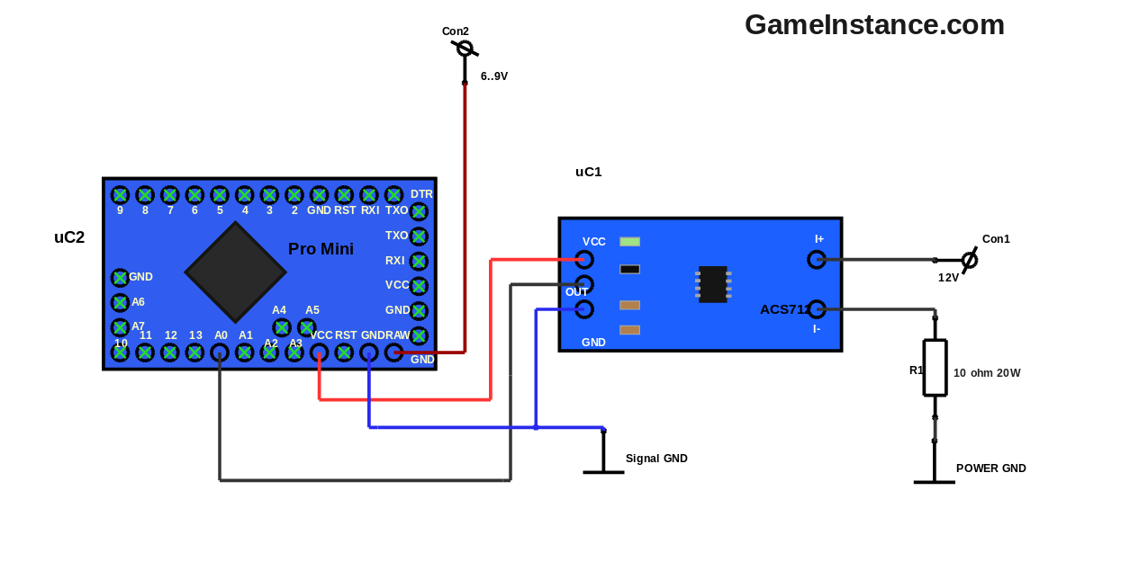 ACS712 breakout board - test setup with Arduino Pro Mini
Connect the Arduino Pro Mini and the ACS712, the 5 amps one, like in the picture below. Connect the high current input for the Hall effect current sensor board. You may use the same GND point for both circuits (the small current and the power one) but I would advise against it. After all, the chip provides galvanic isolation between the two, indulge its ways. Make sure the current consumer can sustain the current it is about to receive. If it is a resistor, it should be rated accordingly. Bulbs, for instance, have voltage ratings so they're easier to use and often the go-to choice.
Compile and upload the code:
static const float VCC_ARDUINO = 5.0;                 // volts
static const int ADC_RESOLUTION = 1024;               // units
static const float CURRENT_SENSOR_RESOLUTION = 0.185; // volts/amp (see datasheet sensitivity)

void setup() {
	//
	Serial.begin(9600);
}

void loop() {
	//
	int value = analogRead(A0);
	float current = ((float)value - ADC_RESOLUTION / 2) / ADC_RESOLUTION;
	current = VCC_ARDUINO * current / CURRENT_SENSOR_RESOLUTION;
	Serial.print(value);
	Serial.print(" => ");
	Serial.print(current);
	Serial.println(" amps");
	delay(1500);
}
You will observe that for no input current the setup will output 512 or 0 amps. The value will oscillate around that value even if there's no current. To cope with that you can either mean the acquired values or use a larger filtering capacitor in parallel with the one on the IC's breakout board. Should you go for any of these options, consider a buffering time prior to actually using the read values.
Finale
On paper, this circuit serves the purpose better than the classic shunt resistor approach. Besides, there's no energy loss and no external amplifying circuitry for it. It also eliminates the tricky common ground point issue. All arguments are in favor of the Hall effect sensor and the first application that comes to mind is the Simple solar battery charger. The controller could measure the state of charge of the battery and make better decisions as to when to start or stop the panel current feed.