Pulse Width Modulation represents a value using two discrete levels: HIGH and LOW, Vcc and GND, +Vdd and -Vss, what have you. The duration of the HIGH state is correlated with the amplitude of the modulating signal. The bigger it is, the longer is the overall HIGH state. All MCUs are capable of generating PWM signals as their way of talking back in analog. This post is about generating PWM audio.
Obtaining a PWM signal from any given value is trivial and involves comparison, usually via an operational amplifier, with a triangular or sawtooth signal. Demodulating a PWM signal is even simpler: a first order low-pass filter, often a series resistor and a capacitor parallel to the output load. As awkward as it may seem, the use of PWM has little to no use in digital processing of signals. ADCs do the hard acquisition work and DACs do the exact reverse. Although all microcontrollers have at least one ADC input, not all have DAC outputs. Thus, PWM offers the means of generating an analog output without the additional cost of DAC circuitry.
With that out of the way, let's look into the PWM generation capabilities the MCUs have. All controllers have internal timers serving various purposes, among which the pulse width modulation. These timers use the clock signal or sub-sampled versions of it to obtain lower frequency signals, by negative powers of two. One such timer increments the value of a register until it reaches a maximum value that's set in another register and then starts over from zero. By doing that it creates of a sawtooth signal, as mentioned before, that is fed into a comparator along with the value to be modulated. The result is a PWM signal with the period of a complete zero-to-zero cycle of the counter register and the HIGH duration of the modulating value.
ATmega328s powering Arduino UNO, Pro, Pro Mini and others, are usually running at 16MHz. With a frequency pre-scaler set to 1, all that mighty speed can be employed for the PWM generation. Needless to say, not all PWM capable pins are equally blessed because not all use the same timers. I'll go with digital pin 3 as it uses a fast PWM timer.
Some math
To obtain an 8 bit resolution, the minimum there is for PCM encoded wave audio, one is left with 62.5KHz for the PWM carrier. That's 16MHz / 8 . That carrier frequency is a bit high and could be lowered by adding bits to the sound resolution. That would also mean jumping from 8 bit/sample to 16bit/sample for the audio data, thus doubling the amount of memory required for storing sounds with the same duration. As a reminder, the ATmega328 has a 2KB SRAM memory, enough for most applications but modest for this one. If you're still considering trading audio length for resolution, take a look at these numbers. The duration of a sample of 8kHz audio is 1 / 8000Hz = 125 microseconds. That may not tell you much but check this one out. The maximum length of an 8kHz 8bit/sample audio sequence is 2048 * 125 microseconds, one quarter of a second. That's short!
Specs
Input audio format: 8bit/sample, delta PCM encoding @ 8kHz, single channel,
Output PWM signal: 62.5kHz, 8bit resolution.
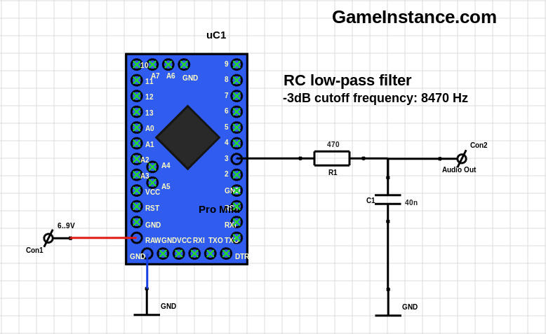 Arduino Pro Mini - PWM Audio Controller schematic
The pin 3 generates the PWM electric signal that can be transformed into audio signal using a speaker, doh. Speakers are built to reproduce only audible frequencies, up to 20kHz, so the 62.5kHz carrier will never be heard. True, but given the spectrum of the signal and the for the sake of rigorousness, I'll be using a first order low-pass filter with a 3dB cutoff frequency of just above 8kHz. That helps reducing the harmonics and minimizing the aliasing distortion. That said, here's the no-longer-Arduino-API program:
#include <util/delay.h>

unsigned char waveData[] = {
  0xff, 0x7f, 0xff, 0xff, 0x7f, 0xff, 0xff, 0xff, 0xff, 0xff, 0xff, 0xff,
	// more than 2000 bytes missing in here
  0xaf, 0x98, 0xab, 0xaf, 0xac, 0x25, 0x23, 0x2e
};
unsigned int waveDataLength = 2036;
unsigned int i = 0;

int main() {
  //
  DDRD |= (1 << DDD3);                      // pin 3 as output
  TCCR2A |= (1 << COM2A1) | (1 << COM2B1);  // non-inverted PWM mode
  TCCR2A |= (1 << WGM21) | (1 << WGM20);    // fast PWM mode
  TCCR2B |= (1 << CS20);                    // no clock frequency reduction
  OCR2A = 255;              // the max count value, giving PWM period
  OCR2B = 0;                // the value to be modulated
  while (true) {
    //
    _delay_us(125);
    OCR2B = waveData[i++];
    if (i >= waveDataLength) {
      //
      i = 0;
      OCR2B = 0;
      _delay_us(1000000);
    }
  }
  return 0;
}
The complete source code: ATmega328_PWM_Audio on GitHub.
Directions
When employed as it is right now the application seems useless. The MCU has a small memory that fills up with audio data, preventing further variables declaration. One could use the audio capability to generate sine wave sounds or other programmable signals. On the other hand, the project might incorporate the SPI slave functionality and become a dedicated audio controller for other memory rich systems. Its memory will be used for buffering purposes and audio length may no longer be a problem, allowing further resolution improvement.