Remember this circuit? Last time it has seen the light of day was early last autumn and that was caused by a poor breadboard contact. Well, now it has a new PCB and a reasonably decent housing.
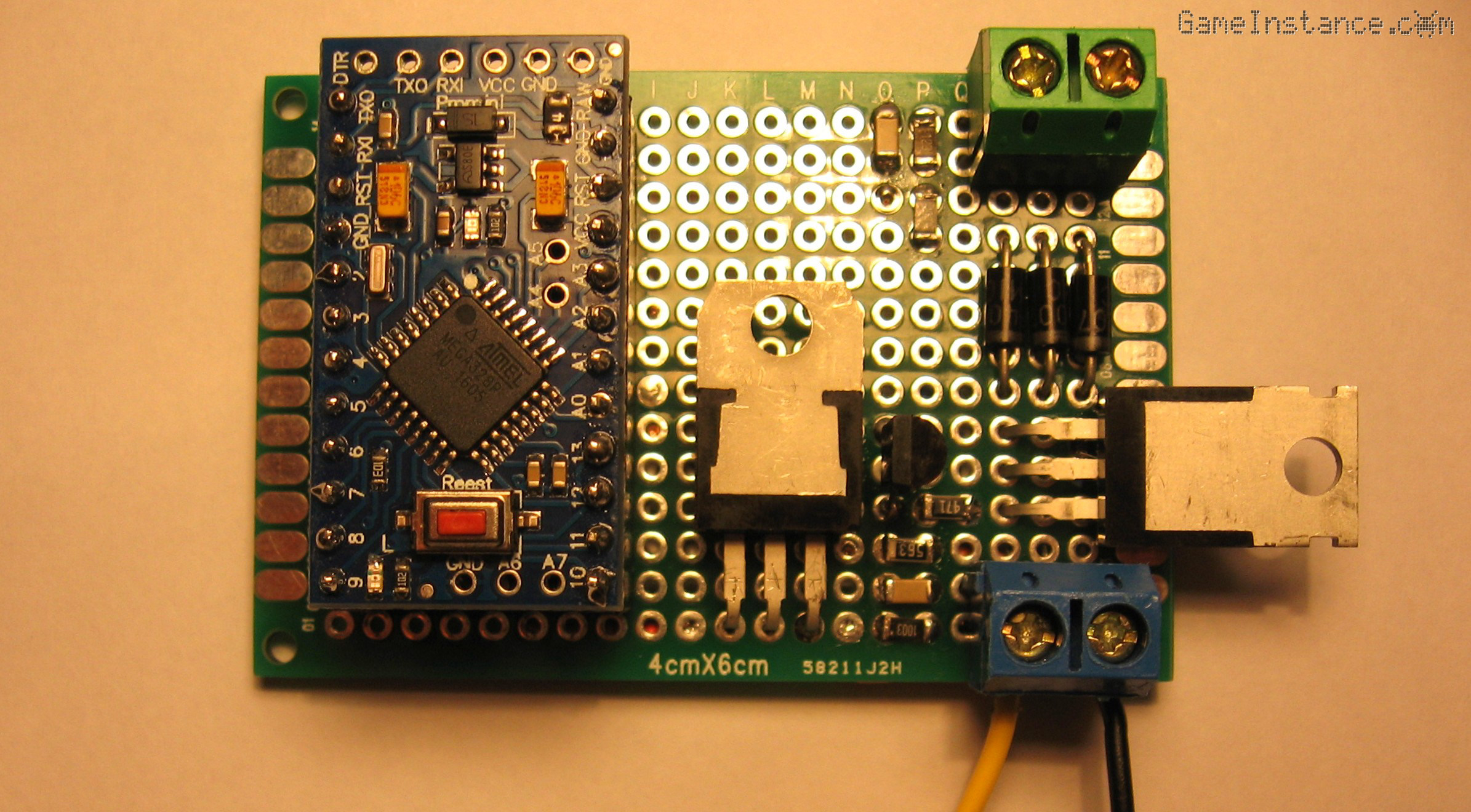 Simple solar battery charger - the component side of the prototyping PCB
Although the Atmega's ADC resolution - even after the voltage divider - would have permitted the installation of a temperature compensation section, for the purpose of this article I deliberately skipped it. The prototype worked without a glitch for several months with no side-effect for the battery. To accurately measure the battery temperature the sensing thermistor needs to be glued to the battery body and its cable pulled out of the charger's casing. That's one cable too much for a circuit as simple as this one and, in case you were thinking, keeping the thermistor inside the charger box won't do either. The small amount of heat produced by the D1-3 diodes, the power transistor and by the regulator would be just enough to negatively influence the reading. Plenty of reasons there.
 Simple solar battery charger - the slightly modified schematics
BOM:
Arduino Pro Mini or a clone
Q1 - IRF4905 - P-Channel MOSFET with RDSon=20 mOhm
Q2 - 2N3904 - NPN transistor, IC=200 mA
D1-3 - UF4007 - IF=1 A, VF=1.7 V
R1 - 100 kOhm
R2 - 12 kOhm
R3 - 1 MOhm
R4 - 500 Ohm
R5 - 10 kOhm
R6 - 150 kOhm
R7 - 55 kOhm
C1,2 - 100nF
Fuse1 - 5 A
Reg1 - LM7805 - 5 V regulator
I've deliberately increased the resistance for the voltage probe branch on the battery side to further reduce the permanent current draw. The ADC input can deal with such small currents. Just like the breadboard prototype, the circuit has the fuse protecting the battery placed outside the box, on a cable fuse mount.
Although revamped, the code relies on the initial version of the Switcharger. That, but not just that, will be detailed in a future article.
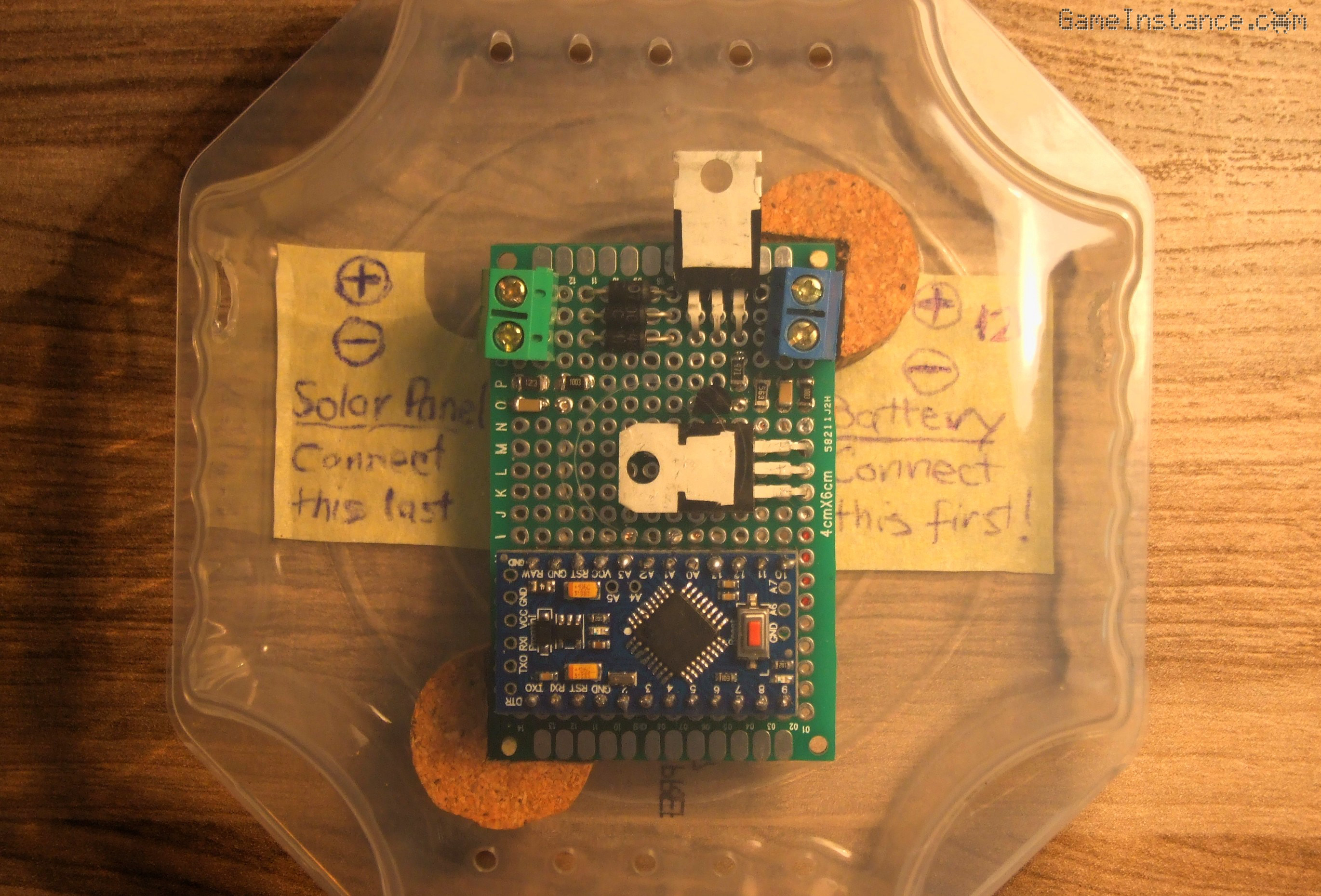 Simple solar battery charger - the prototyping PCB in a plastic cheese box
Despite the use of a prototyping PCB and the fancy SMD resistors and capacitors, the circuit still costs less than 3 dollars, which is also less than the cheese block that used to be in that transparent box. I'm not proud of the through-hole and surface-mount mixture, especially on these kind of boards, but that was a fun experiment. Oh, and the whole shebang takes less four hours of component soldering and cable routing. DIY at its best!