There's no simpler Arduino application than probing a battery cell's voltage. Whether they're 1.2V, 1.5V or 3.7V cells, they all fit in the Arduino's measurable ballpark. However, ADC precision is out of the question with a 4.9 mV resolution. Oversampling the Atmega328 not only works, it does wanders. It squeezes the MCU's juices reaching down to 76uV. Precision is never enough though. This article is about obtaining up to four times more the measurement resolution using an op-amp in differential setup.
First question
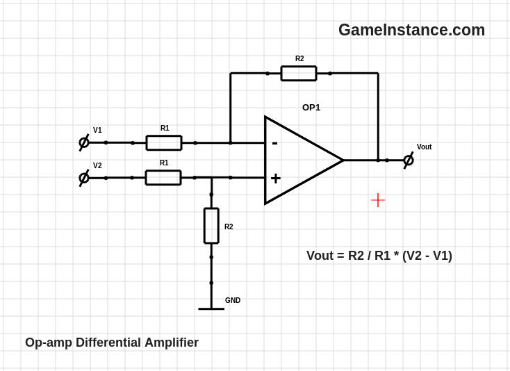
that pops in mind is why not a simple non-inverting amplifier?
The answer is also simple: the 5V ADC range isn't enough to achieve high gain factors. For a 1.2V NiMH cell, a factor of 4x translates in 4.8V for the ADC to read. However, the battery often surpasses 1.35V, throwing the Vout beyond ADC's upper limit. Not to mention, Li-Ion battery cells average at 3.7 volts. For them the factor will be just shy of 1x.
Second question
A differential amp implies two voltages, one of which is the battery's. What's the second?
The second is a fix reference voltage that is few millivolts smaller than the lowest acceptable battery voltage. A completely discharged NiMH battery may reach as low as 1V making 0.9V a good reference. Given that a fully charged battery might have up to 1.5V, a theoretical amplification factor of 8x can be attained. (1.5 - 0.9) * 8 = 4.8V < 5V
Unless you're planning on using an instrumentation amplifier, consider designing your circuit such that the Vout avoids the regions near the power rails. If you're using Arduino, most likely the power rails for the Op-amp will be Vcc = 5V and GND = 0V. So far I've never seen a LM358 output diving below 30mV or raising above 3.7V.
Test rig
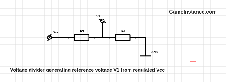
aims at precision measuring a 1.2V NiMH battery using an Atmega328 Arduino powered at 5V. For generating the V1 reference voltage, one must choose from a set of standard resistor values. As such, R3 = 5k1 and R4 = 1k give a theoretical value of 819mV and a 823mV measured one. Selecting the R1 = 51k and R2 = 220k yields an amplification factor of 4.31x. Note that the current flowing from V1 to GND via any path surrounding the op-amp is 45 times smaller than the current through the (R3, R4) voltage divider. The smaller, more stable the V1 will be throughout the measurement.
One can use a potentiometer connected between Vcc and GND with the brush giving a test voltage in the battery cell voltage range.
| # | V battery | Vout (measured) | Vout (calculated) | Error |
|---|---|---|---|---|
| 1 | 1 | 0.794 | 0.763 | 0.031 |
| 2 | 1.05 | 0.995 | 0.978 | 0.017 |
| 3 | 1.10 | 1.195 | 1.194 | 0.001 |
| 4 | 1.15 | 1.405 | 1.409 | -0.004 |
| 5 | 1.20 | 1.634 | 1.625 | 0.009 |
| 6 | 1.25 | 1.901 | 1.840 | 0.061 |
| 7 | 1.30 | 2.054 | 2.056 | -0.002 |
| 8 | 1.35 | 2.281 | 2.271 | 0.010 |
| 9 | 1.40 | 2.492 | 2.487 | 0.005 |
| 10 | 1.45 | 2.695 | 2.702 | -0.007 |
Comparing the (voltmeter) measured output voltages against the calculated ones gives consistently small errors. This confirms that the circuit works and gives a liner output - as it should - in the desired voltage range.
Now let's take this test one step further. Hook the potentiometer generated voltage V2 to Arduino pin A0, Vout to pin A1 and the reference voltage V1 to A3. Run the following sketch and capture the serial output into a file.
const float VCC_ARDUINO = 5.0;
const float ADC_RESOLUTION = 1024.0;

float Vref = 0, Vin = 0, Voutm = 0, Voutd = 0;

float readVoltage(int pin) {
  //
  return VCC_ARDUINO * analogRead(pin) / ADC_RESOLUTION;
}

void setup() {
  // put your setup code here, to run once:
  Serial.begin(9600);
}

void loop() {
  // put your main code here, to run repeatedly:
  Vin = readVoltage(A0);
  Voutm = readVoltage(A1);
  Vref = readVoltage(A2);
  // Amp-factor = 4.31 = 220k / 51k
  // Vref = 0.823 V
  Voutd = 4.31 * (Vin - 0.823);
  Serial.print(Vref, 4);
  Serial.print(", ");
  Serial.print(Vin, 4);
  Serial.print(", ");
  Serial.print(Voutm, 4);
  Serial.print(", ");
  Serial.print(Voutd, 4);
  Serial.println(", ");
  delay(200);
}
Put on a chart along with its determined value, Vout looks like this:
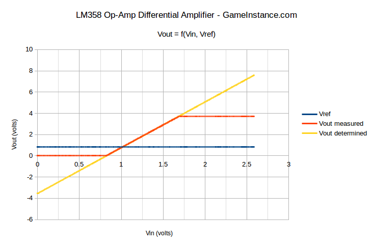
The measured Vout starts at 0.0293 volts and ends at 3.7305 volts. Accepting the limitations of LM358, we're left with an output range of 3.7012 volts (3.7305 - 0.0293) for an input of 0.677 volts (1.5 - 0.823). This gives a maximum practical amplification factor of 5.47x bringing the default 10 bit ADC resolution of the 5V Arduino below 1mV, at 892uV.
Conclusion
The op-amp solution may seem extreme in most of the cases. However, the gain in resolution is imperative for detecting the -dV condition towards the end of the constant-current charging process for NiMH battery cells. The bill of materials should not exceed few nickels. The PCB footprint is also low. That's not so extreme after-all.