This article walks you through the complete circuit of the UV exposure box, including the Arduino schematic and the Arduino code. Fragments of the initial idea were briefly presented in part 1 and part 2, some of them have changed meanwhile and some other have not yet been mentioned.
The UV-Box 400's schematic is divided in two main parts. The first employs high voltage to power the UV LEDs and the second uses 5V circuitry to control the exposure time.
The 5V circuit
is composed of the Atmega MCU controlling the STDT relay that turns the LEDs on. It includes a LCD that displays elapsed time and state of the box, four buttons and the Hall effect sensor.
The 5V Vcc can be produced by a small USB charger. If you don't have one lying around, you can find ones for as low as 1 USD. They don't have to be powerful, 0.5A is more that the application needs. Surely it will be small enough to fit in the electrics compartment. However, I've obtained that voltage from a low current 12V power supply from a disabled device using an AMS1117-5 regulator.
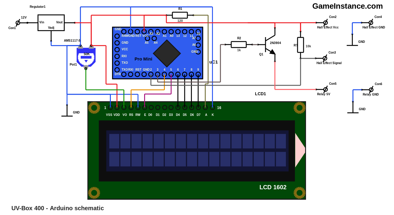
The automation is rather simple and the code for it takes around 6.5 KB of program storage. The RAM usage is well within the 1 KB, so the MCU used may very well be the Atmega 168. If you decide to use a different MCU, make sure you have a minimum number of 7 logic output pins to control the LCD and the relay and at least 5 inputs for the buttons and the Hall effect sensor. The two lines of 16 chars suffice for displaying the remaining time, the total exposure time, the state and brief instructions. For details on how to connect it, visit the Hitachi 1602 LCD article.
The four buttons, though not figured in the schematic above, are using pull-up resistors and connect to GND when pushed the following Arduino pins:
Red button -------- pin 10Green button ------ pin 11
Blue button ------- pin 12
Yellow button ----- pin 13
The relay needs 5 V and draws around 40 mA to operate. That current cannot be given by the Atmega's output pin - it's max. value is 20 mA - so a bipolar transistor will be needed to switch the relay current on and off. The Hall effect sensor connects to the controlling board via a 3 pin header plug. In a similar manner, the relay wires go to a 2 pin header.
From the high voltage compartment to the Arduino compartment a three wire cable is routed. It should be insulated twice to avoid accidental contact with the high voltage wires as it passes below the LED boards and through the cable auxiliary chamber. The first wire powers the MCU board with 5 or 12 volts, depending on your implementation, the second is the relay 5V command line and the last is GND, which is common for both.
The high voltage circuit
occupies a completely separate compartment that is closed at all times with screws that touch nothing but wood. The 240V AC line feeds the rectifier and it is interrupted only by the relay. Although not pictured, a fuse of 0.25A should be placed in between.
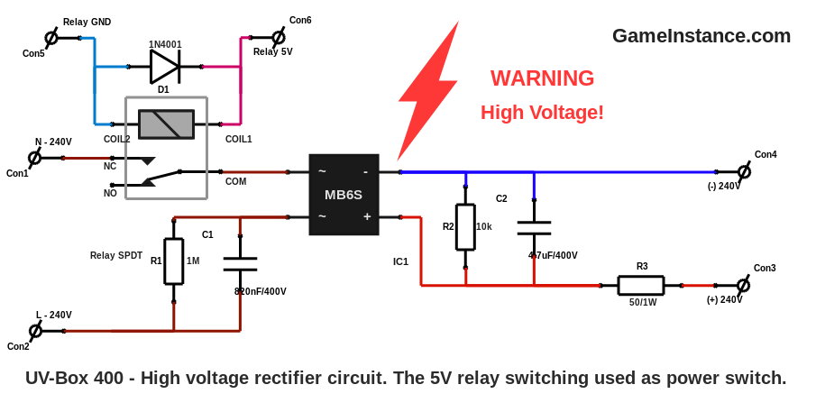
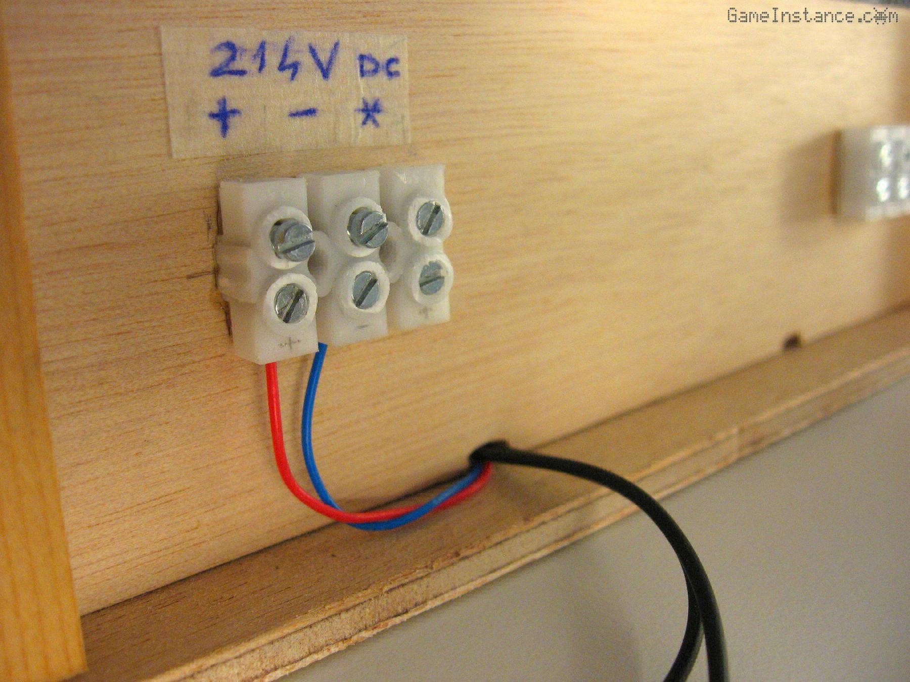
From the rectifier, a pair of cables pass below the lower LED board and go to the cable auxiliary chamber at the back of the box. The two wires will connect there with the three LED circuits. As a reminder, the connector marked with the star sign joins the upper and lower halves of LED circuits to complete the third series.
Warning:
This project involves HIGH VOLTAGE! Touching a high voltage live wire is DEADLY! Please take proper precautions if you are attempting to reproduce it.
The Arduino code
consists of a simple finite-state machine driving the relay output and displaying times and states on the LCD. In a nutshell, the Hall effect sensor turns the UV light as soon as the box lid is lifted, avoiding the accidental exposure. The green button increases the exposure time and the blue decreases it with 5 seconds steps. The red button starts the exposure, the yellow pauses and resumes it. With no further ado, the Arduino sketch:
/*
 * UV-Box 400
 * UV double exposure box using three high-voltage series
 * circuits totaling 200 LEDs, controlled using Atmega168.
 *
 * GameInstance.com
 * 2018
 */
#include <LiquidCrystal.h>
#include <EEPROM.h>

static const unsigned char RED_BUTTON = 10;
static const unsigned char GREEN_BUTTON = 11;
static const unsigned char BLUE_BUTTON = 12;
static const unsigned char YELLOW_BUTTON = 13;
static const unsigned char LID_SENSOR = 2;
static const unsigned char RELAY_OUT = 3;

static const bool LID_SENSOR_ENABLED = true;

struct HourMinuteSecond {

  unsigned int hours, minutes, seconds;

  HourMinuteSecond(): hours(0), minutes(0), seconds(0) {
    //
  }
  void Init(unsigned int h = 0, unsigned int m = 0, unsigned int s = 0) {
    //
    hours = h;
    minutes = m;
    seconds = s;
  }
  bool EEPROMRead(unsigned int address) {
    //
    hours = EEPROM.read(address);
    minutes = EEPROM.read(address + 1);
    seconds = EEPROM.read(address + 2);
    if ((hours > 9) || (minutes > 59) || (seconds > 59)) {
      //
      Init(0, 8, 30);
      return false;
    }
    //
    return true;
  }
  void EEPROMWrite(unsigned int address) {
    //
    EEPROM.write(address, hours);
    EEPROM.write(address + 1, minutes);
    EEPROM.write(address + 2, seconds);
  }
  unsigned int ToSeconds() {
    //
    return seconds + minutes * 60 + hours * 3600;
  }
  void FromSeconds(unsigned int sec) {
    //
    seconds = sec % 60;
    minutes = (sec / 60) % 60;
    hours = sec / 3600;
  }
  void Increment(int m = 0, int s = 5) {
    //
    unsigned long int sec = ToSeconds() + s + m * 60;
    if (sec > 35999) {
      // overflowing 9:59:59
      sec = s < 0 ? 0 : 35995;
    }
    FromSeconds(sec);
    EEPROMWrite(0);
  }
};

unsigned int state = 0;
unsigned long int elapsed_seconds, start_ts, button_ts;
HourMinuteSecond total_hms, elapsed_hms;

LiquidCrystal lcd(4, 5, 6, 7, 8, 9);

namespace LCD {

  void Clear () {
    //
    lcd.setCursor(0, 0);
    lcd.print("                ");
    lcd.setCursor(0, 1);
    lcd.print("                ");
  }

  void Splash() {
    //
    lcd.setCursor(0, 0);
    lcd.print("GameInstance.com");
    lcd.setCursor(3, 1);
    lcd.print("UV-Box 400");
  }

  void DisplayHMS(HourMinuteSecond &hms, unsigned int x, unsigned int y, String message = "") {
    //
    static unsigned int flicker_count = 0;
    lcd.setCursor(x, y);
    if (message.length() > 0) {
      //
      flicker_count ++;
      if (flicker_count > 100) {
        //
        flicker_count = 0;
      }
      if (flicker_count <= 20) {
        //
        while(message.length() < 8) {
          //
          message += " ";
        }
        lcd.print(message);
        return;
      }
    }
    lcd.print(hms.hours);
    lcd.print(":");
    lcd.print(hms.minutes <= 9 ? "0" : "");
    lcd.print(hms.minutes);
    lcd.print(":");
    lcd.print(hms.seconds <= 9 ? "0" : "");
    lcd.print(hms.seconds);
    lcd.print(" ");
  }

  void DisplayTimeLine(String message = "") {
    //
    LCD::DisplayHMS(elapsed_hms, 0, 0, message);
    lcd.setCursor(8, 0);
    lcd.print(" ");
    LCD::DisplayHMS(total_hms, 9, 0);
  }

  void SensorState(bool R, bool G, bool B, bool Y, bool L) {
    //
    lcd.setCursor(0, 1);
    lcd.print("R");
    lcd.setCursor(1, 1);
    lcd.print(R ? "1" : "0");

    lcd.setCursor(3, 1);
    lcd.print("G");
    lcd.setCursor(4, 1);
    lcd.print(G ? "1" : "0");

    lcd.setCursor(6, 1);
    lcd.print("B");
    lcd.setCursor(7, 1);
    lcd.print(B ? "1" : "0");

    lcd.setCursor(9, 1);
    lcd.print("Y");
    lcd.setCursor(10, 1);
    lcd.print(Y ? "1" : "0");

    lcd.setCursor(12, 1);
    lcd.print("L");
    lcd.setCursor(13, 1);
    lcd.print(L ? "1" : "0");
  }
}

void setup() {
  //
  pinMode(RED_BUTTON, INPUT);
  pinMode(GREEN_BUTTON, INPUT);
  pinMode(BLUE_BUTTON, INPUT);
  pinMode(YELLOW_BUTTON, INPUT);
  pinMode(LID_SENSOR, INPUT);
  pinMode(RELAY_OUT, OUTPUT);
  digitalWrite(RELAY_OUT, LOW);
  lcd.begin(16, 2);
}

void loop() {
  //
  if (button_ts == 0) {
    //
    if (digitalRead(GREEN_BUTTON) == LOW) {
      // green button down
      button_ts = millis();
      total_hms.Increment(0, 5);
    }
    if (digitalRead(BLUE_BUTTON) == LOW) {
      // blue button down
      button_ts = millis();
      total_hms.Increment(0, -5);
    }
  } else {
    //
    if ((digitalRead(GREEN_BUTTON) == HIGH)
      && (digitalRead(BLUE_BUTTON) == HIGH)) {
      // all time change buttons up
      button_ts = 0;
    }
    if (millis() - button_ts > 500) {
      // time change buttons change expired
      button_ts = 0;
    }
  }

  if (state == 0) {
    // init
    LCD::Clear();
    LCD::Splash();
    delay(2000);
    state = 100;
  }
  if (state == 100) {
    //
    total_hms.EEPROMRead(0);
    elapsed_hms.Init();
    elapsed_seconds = 0;
    state = 1;
  }
  if (state == 1) {
    // ready to start
    state = 2;
  }
  if (state == 2) {
    //
    if (LID_SENSOR_ENABLED
      && (digitalRead(LID_SENSOR) == HIGH)) {
      // lid open
      LCD::DisplayTimeLine("Lid open");
      lcd.setCursor(0, 1);
      lcd.print("Close to prepare");
    } else {
      //
      LCD::DisplayTimeLine("Ready");
      lcd.setCursor(0, 1);
      lcd.print("  Red to start  ");

      if (digitalRead(RED_BUTTON) == LOW) {
        // red button down
        state = 3;
      }
    }
  }
  if (state == 3) {
    // start: exposure start
    start_ts = millis();
    digitalWrite(RELAY_OUT, HIGH);
    lcd.setCursor(0, 1);
    lcd.print("Yellow to pause  ");
    state = 4;
  }
  if (state == 4) {
    //
    if (digitalRead(RED_BUTTON) == HIGH) {
      // red button up again
      state = 5;
    }
  }
  if (state == 5) {
    //
    unsigned long int actual_elapsed_seconds = elapsed_seconds + (millis() - start_ts) / 1000;
    if (actual_elapsed_seconds > total_hms.ToSeconds()) {
      // time's up
      state = 20;
    } else {
      //
      elapsed_hms.FromSeconds(actual_elapsed_seconds);
      LCD::DisplayTimeLine("Exposing");

      if (LID_SENSOR_ENABLED
        && (digitalRead(LID_SENSOR) == HIGH)) {
        // lid open
        state = 11;
      }

      if (digitalRead(YELLOW_BUTTON) == LOW) {
        // yellow button down
        state = 6;
      }
    }
  }
  if (state == 6) {
    // pause: exposure stop
    digitalWrite(RELAY_OUT, LOW);
    elapsed_seconds += (millis() - start_ts) / 1000;
    lcd.setCursor(0, 1);
    lcd.print("Yellow to resume ");
    state = 7;
  }
  if (state == 7) {
    //
    if (digitalRead(YELLOW_BUTTON) == HIGH) {
      // yellow button up again
      state = 8;
    }
  }
  if (state == 8) {
    //
    LCD::DisplayTimeLine("Paused");

    if (digitalRead(YELLOW_BUTTON) == LOW) {
      // yellow button down
      state = 9;
    }
  }
  if (state == 9) {
    // resumed: exposure start
    digitalWrite(RELAY_OUT, HIGH);
    start_ts = millis();
    lcd.setCursor(0, 1);
    lcd.print("Yellow to pause  ");
    state = 10;
  }
  if (state == 10) {
    //
    if (digitalRead(YELLOW_BUTTON) == HIGH) {
      // red button up again
      state = 5;
    }
  }
  if (state == 11) {
    // lid open: exposure stop
    digitalWrite(RELAY_OUT, LOW);
    elapsed_seconds += (millis() - start_ts) / 1000;
    lcd.setCursor(0, 1);
    lcd.print("Close to resume ");
    state = 12;
  }
  if (state == 12) {
    //
    LCD::DisplayTimeLine("Lid open");

    if (LID_SENSOR_ENABLED
      && (digitalRead(LID_SENSOR) == LOW)) {
      // lid closed
      state = 13;
    }
  }
  if (state == 13) {
    // lid closed: exposure start
    digitalWrite(RELAY_OUT, HIGH);
    start_ts = millis();
    lcd.setCursor(0, 1);
    lcd.print("Yellow to pause  ");
    state = 5;
  }

  if (state == 20) {
    // time exipred: exposure stop
    digitalWrite(RELAY_OUT, LOW);
    elapsed_seconds += (millis() - start_ts) / 1000;
    lcd.setCursor(0, 1);
    lcd.print("Open the lid    ");
    state = 21;
  }
  if (state == 21) {
    //
    LCD::DisplayTimeLine("Finished");

    if (digitalRead(LID_SENSOR) == HIGH) {
      // lid open
      state = 100;
    }
  }

  delay(50);
}
Noteworthy is the fact that the exposure time set by the user is stored in the EEPROM memory. However, a single entry is stored. That means the user has to change the time by hand for multiple uses of the UV box - curring etch mash or solder mask. That should constitute the base of further updates.
Keep an eye out for updates on Github.
Milestone 5
marks the completion of this project. If you choose to reproduce it as it is, take appropriate protection measures when handling the high voltage circuit sections and wear UV filtering glasses when playing with the UV LEDs. You could tone-down hazards by using a 12V, 4A power supply fitted in the electrics compartment and powering the LEDs in series of 3, much like most of the DIY UV boxes out there. I hope you've enjoyed reading and that you'll find it useful in your similar endeavors. Have fun!