Since most of the music we listen to nowadays comes from digital sources, it seems reasonable processing it digitally as well. This article presents the C++ STL implementation of a digital filter in direct form I and II, underlining the fact that this cannot be used for Arduino or most MCUs due to the use of standard library data structures.
The common ground
for both implementations consists of the FilterBase virtual template class. It offers leverage for initialization, state reset as well as the backbone for the filtering mechanism. The template gives it a degree of liberty in choosing the data types for the signal and filter coefficients.
template <class T, class W> class FilterBase {

    public:

        FilterBase() {}
        virtual ~FilterBase() {}

        virtual void Init(vector<W> a, vector<W> b) {
            //
            m_a = a;
            m_b = b;
            if (m_a.at(0) != 1.0) {
                //
                throw(1);
            }
            this->Reset();
        }
        virtual void Reset() = 0;
        virtual W Execute(T x) = 0;


    protected:

        /// filter coefficients
        vector<W> m_a, m_b;
};
The class features two protected vectors for storing the A and B filter coefficients. Being purely virtual means that it needs to be implemented. The following two classes do just that.
Direct form I
has the advantage of simplicity at the cost of twice the number of memory elements storing delayed signal samples.
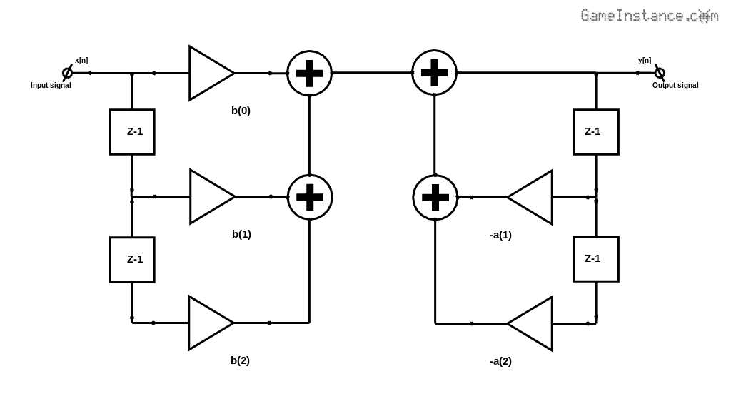 Direct form I implementation of a biquad digital filter.
With not further ado, the FilterDirectI template class implements the Reset method by removing all delay elements and creating new ones instead. The Execute method has a time complexity that grows linearly with the filter's order. The code is straightforward and follows the schematic above.
template <class T, class W> class FilterDirectI : public FilterBase<T, W> {

    public:

        FilterDirectI() : FilterBase<T, W>() {}
        virtual ~FilterDirectI() {}

        void Reset() {
            //
            m_da.erase(m_da.begin(), m_da.end());
            m_db.erase(m_db.begin(), m_db.end());
            m_da.resize(FilterBase<T, W>::m_a.size() - 1);
            m_db.resize(FilterBase<T, W>::m_b.size() - 1);
        }
        W Execute(T x) {
            //
            W sum(0);
            for (std::vector<int>::size_type i = m_db.size() - 1; i != static_cast<std::vector<int>::size_type>(-1); i --) {
                //
                sum += FilterBase<T, W>::m_b.at(i + 1) * m_db.at(i);
                m_db.at(i) = (i == 0) ? x : m_db.at(i - 1);
            }
            sum += FilterBase<T, W>::m_b.at(0) * x;
            for (std::vector<int>::size_type i = m_da.size() - 1; i != static_cast<std::vector<int>::size_type>(-1); i --) {
                //
                sum += -FilterBase<T, W>::m_a.at(i + 1) * m_da.at(i);
                m_da.at(i) = (i == 0) ? sum : m_da.at(i - 1);
            }
            return sum;
        }


    private:

        /// delay element vectors
        vector<W> m_da, m_db;
};
I just had to play with the size_type iteration variable. Although the compiler warns no more and the code is portable, the result isn't quite human readable. However, I've left it as is for educational purposes.
Direct form II
is a tad trickier to grasp but it runs on less memory than its Direct Form I counterpart. The FilterDirectII does not follow the schematic and instead it uses a second summation variable to generate the result.
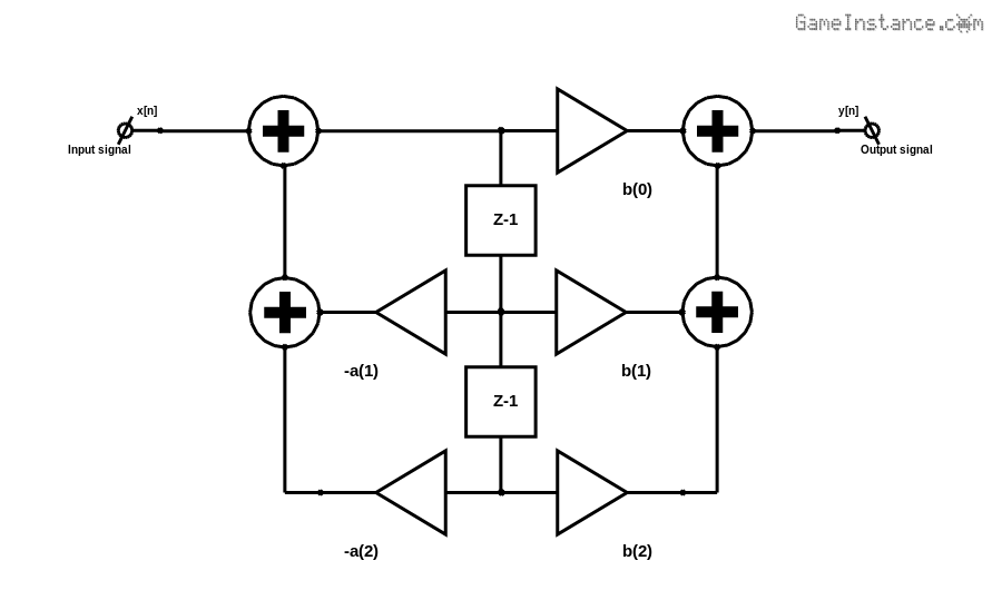 Direct form II implementation of a biquad digital filter.
The iteration variable is unsigned long for this example, again for the sake of experimentation. The C++11 developer in you might argument for the use of auto &i. This isn't feasible in this case as the iteration is made over multiple vectors using offset indices.
template <class T, class W> class FilterDirectII : public FilterBase<T, W> {

    public:

        FilterDirectII() : FilterBase<T, W>() {}
        virtual ~FilterDirectII() {}

        void Reset() {
            //
            m_v.erase(m_v.begin(), m_v.end());
            m_l = (FilterBase<T, W>::m_a.size() > FilterBase<T, W>::m_b.size()) ?
                FilterBase<T, W>::m_a.size() - 1 : FilterBase<T, W>::m_b.size() - 1;
            m_v.resize(m_l);
        }
        W Execute(T x) {
            //
            W sum1(x), sum2(0);
            for (unsigned long i = m_l - 1; i != static_cast<unsigned long>(-1); i --) {
                //
                if (i < FilterBase<T, W>::m_a.size() - 1) {
                    //
                    sum1 += -FilterBase<T, W>::m_a.at(i + 1) * m_v.at(i);
                }
                if (i < FilterBase<T, W>::m_b.size() - 1) {
                    //
                    sum2 += FilterBase<T, W>::m_b.at(i + 1) * m_v.at(i);
                }
                m_v.at(i) = (i == 0) ? sum1 : m_v.at(i - 1);
            }
            return (sum1 * FilterBase<T, W>::m_b.at(0) + sum2);
        }


    private:

        /// delay element vector
        vector<W> m_v;
        /// length pf delay element vector
        unsigned long m_l;
};
The Reset methods could have used vector resize followed by element level reset. Remember that resizing is necessary since the method is called within Init. Again, for the fun of it I chose to erase the vectors and recreate the elements at the given size. There's not really a huge penalty here since the Init and Reset are only called punctually.
Test program
implements a biquad filter with zero magnitude frequency response designed to alter the phase of the signal. Details can be found in the previous article.
#define PI 3.14159265

typedef complex<double> Complex;

typedef FilterDirectII<double, Complex> LFilter;


int main() {
    //
    double r = 0.9985;
    LFilter iir;
    double omega = 2 * PI * 40 / 44100;
    vector<Complex> a;
    a.push_back(Complex(1.0, 0.0));
    a.push_back(Complex(0.0, 2.0 * r * sin(omega)));
    a.push_back(Complex(r*r, 0.0));
    vector<Complex> b;
    b.push_back(Complex(1.0, 0.0));
    b.push_back(Complex(0.0, -2.0 / r * sin(omega)));
    b.push_back(Complex(-1/(r*r), 0.0));
    iir.Init(a, b);
    Complex y;
    for (int i = 0; i < 10; i ++) {
        //
        y = iir.Execute(1);
        cout << y.real() << " \n";

    }
    return 0;
}
The direct form II template class is instantiated for double precision for the input signal and complex doubles for the filter coefficients.
To conclude
Obviously both solutions give the same step response. The first is resilient to internal overflow and the second uses less memory. None of them is less sensitive to round-off errors when it comes to higher order functions but this issue can be alleviated by chaining multiple second order filters. It is pointless getting into further details here. Nonetheless, it is worth mentioning that other filter implementations exist, such as the transposed direct forms, and have certain advantages.
The C++ program does what's supposed to do but if you're thinking of porting this to Arduino, you should know that STL data structures are not natively available. Some attempts have been made in this direction but I don't advise any of them for a task as simple as this.