This is a quick introductory article on driving DC electric motors using small signals produced by micro-controllers, such as the ATmega, PIC or STM32. Turning a motor on and off can be achieved only with a power transistor and, optionally, a signal amplifier transistor but managing the direction of its rotation implies an H-Bridge.
Basic function
of the H-bridge is allowing the current to flow in one direction or the other through a DC motor, thus controlling its rotation direction. A bipolar transistor implementation is proposed below.
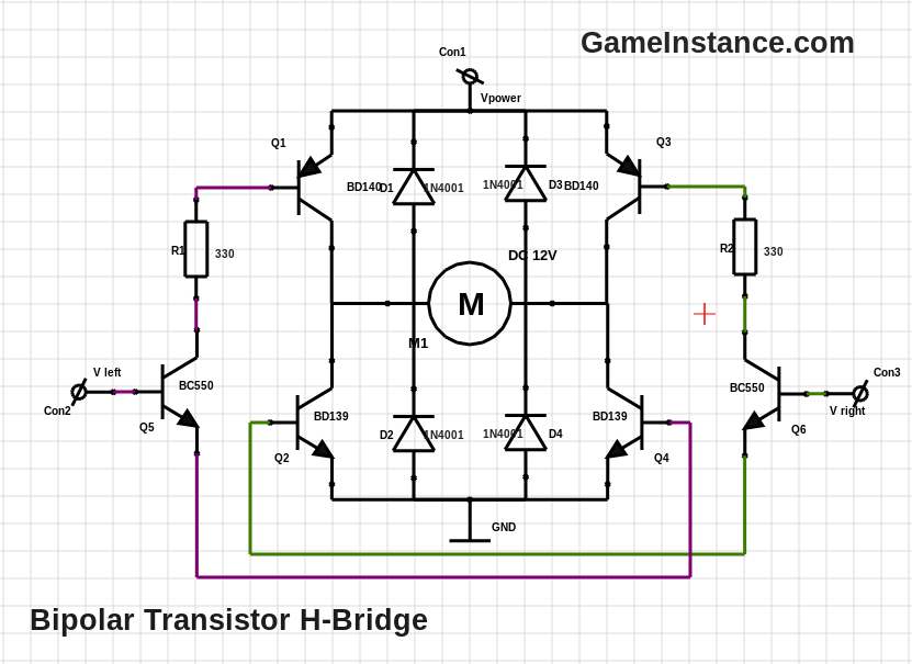
When two diagonal transistors are on, Q1 and Q3 for example, the other two, Q2 and Q4, are off. This creates a low impedance path for the current to follow through the motor. To drive it in reverse, the Q2 and Q4 must be on while Q1 and Q3 be off.
Restriction
Transistors interconnecting the motor must not short-circuit the power rails. This means that Q1 and Q2 shouldn't be on at the same time. Same goes for Q3 and Q4. This requires a careful design of the circuit or the MCU sketch that controls the H-bridge. For the circuit above this rule translates to Vleft and Vright must not be HIGH at the same time.
Diodes
Motors and actuators in general present rather high inductances. This combined with high current and quick switching, yields high transient voltages at their terminals. The formula below will give a hint about the voltage spike values.
Because transistors don't turn on (or off) at the same time, one of them will end-up dealing with the spike plus the voltage from the power supply. Most of the times the total value will exceed the VCE or VEC ratings for the switching transistor, with destructive effects.
That is the reason the D1-4 diodes are placed in parallel with the collector-emitters. Any spike generated by the motor will be quickly short-circuited, thus protecting the transistor. Needless to say, the diodes should have a voltage and current rating suitable for this purpose. Also an important factor is diode's reaction time. The faster it intercepts the spike, the better. Schottky diodes are better in this aspect - the 1N4001 isn't ideal for this application.
Driver
The H-Bridge is driven by Q5 and Q6 in one direction of the other by saturating diagonal switching transistors. Notice the presence of current limiting resistors R1 and R2. Also, it would wise to add a current limiting resistor between the base of Q5 and Q6 when using output signals from MCUs.
Overall
H-Bridges help DC motors turn both ways. They're not that difficult to get right and make a fun experiment. However, it would be preferable to use purpose built H-Bridge chips. For high current applications one should use H-Bridge drivers combined with high power transistors.