Knowing the code words, the binary encoding, the frequency of the modulated ASK signal and the break duration, can help reproduce the signals of any 433 MHz remote control with general purpose emission-reception modules. However, both carrier frequency and signal strength play important roles that affect the usability of any custom design.
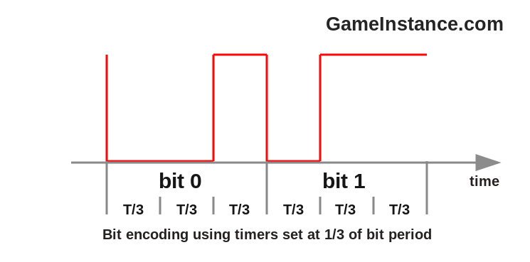
This is a follow-up of the previous post on Decoding 433 MHz Remote Control Signals. As a reminder, the remote was sending 15 code words of 37 bits each, separated by 40 ms low level breaks. Each bit was encoded using 1/3 and 2/3 duty cycle pulses of 1.056 ms.
The RF circuit
centers around the 433 MHz ASK transmitter which is controlled by pin 13 of an Atmega328p. The radio module is powered directly from the 9-12 volt power supply while the Arduino Pro Mini board gets its 5 volt from an external 7805 regulator. The antenna is a half-wave dipole composed of two 15-17 cm long wires opposing each other. One is connected to the ANT pin while the other goes to the common GND point. This configuration achieves the maximum signal strength.
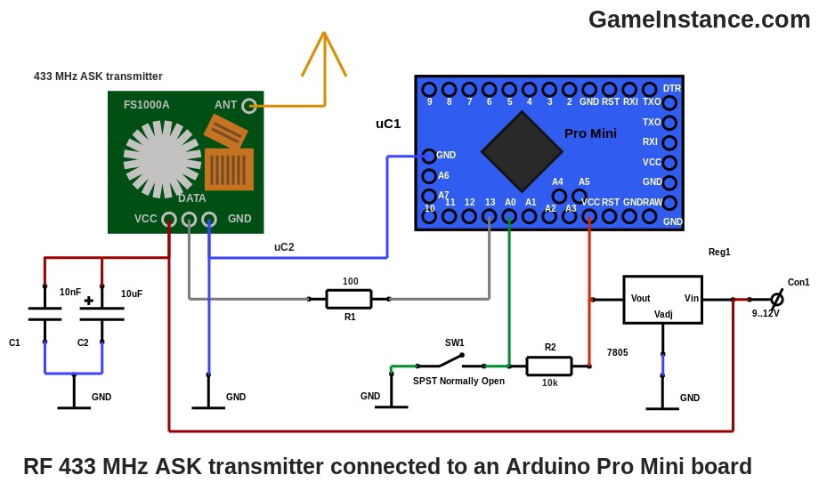
To maintain a reserve of energy for the sudden bursts of RF signals, an electrolytic-ceramic decoupling capacitor duet was placed in parallel with the main power supply, near-by the radio module's power pins. There's also the SW1 button that is used for triggering code transmission.
The code
relies on a timer interrupt internal trigger. After trying various approaches - including delayMicrosecond() and micros() in while loops - this one seems to generate consistently precise duty cycle signals. Configuring the timer to trigger every third of a bit period was easy. The prescaler was set at 64 and the counter to 88. At a clock frequency of 16 MHz that meant 354 (1056/3) microseconds.
On each such event a new position of the bits array is presented at the output pin, according to the current indication from the code array. The finite-state machine has three useful states of which the first one is waiting for the button to be pressed. The second does a rather obscure operation of sending some meaningless longer duration signals. Although the complete explanation for this escapes the scope of this article, the short one is this: prepares the receiver's amplifier for the magnitude of the signal that it is about to receive. The third generates the code words and the breaks and then passes the flow to the first state. The interrupt routine containing the state machine is light-weight even for the limited Atmega328p. With no further addo, the code:
#include <avr/io.h>
#include <avr/interrupt.h>

const byte BUTTON = A0;
const byte SIGNAL = 13;

const byte CODE_LENGTH = 37;                          // bits
const byte BREAK_LENGTH = 38;                         // "null" bits
const byte TOTAL_LENGTH = CODE_LENGTH + BREAK_LENGTH; // bits
const byte WORD_COUNT = 15;                           // words
const byte BIT_CHUNKS = 3;                            // parts composing a bit
const byte code[] = {0,0,1,1,0,1,0,1,0,1,0,1,0,1,1,0,0,1,1,1,1,0,0,1,0,1,1,1,1,1,1,1,1,1,1,1,1};
const byte bits[][BIT_CHUNKS] = {{0,0,1}, {0,1,1}, {0,0,0}}; // 0, 1 and "null"

volatile byte state = 0, pos = 0, slice = 0, cnt = 0, value = 0;

int main(void) {
  // setting timer2 to trigger an interrupt every 352 us @ 16 MHz CLK

  OCR2A = 88;              // the counter max threshold
  TCCR2A |= (1 << WGM21);  // CTC mode
  TIMSK2 |= (1 << OCIE2A); // compare match interrupt
  TCCR2B |= (1 << CS22);   // prescaler to 64 and PWM start
  sei();                   // interrupts enabled

  while (1) {
    // do nothing
  }
}

ISR (TIMER2_COMPA_vect) {
  // triggered every 352 microseconds

  if (state == 0) {
    // waiting for button press
    if (digitalRead(BUTTON) == LOW) {
      //
      state = 1;
    }
  }

  else if (state == 1) {
    // transmission variable initialization
    slice = 0;
    cnt = 0;
    value = 0;
    state = 2;
  }

  else if (state == 2) {
    // "waking-up" the receiver
    if (cnt >= 9) {
      //
      digitalWrite(SIGNAL, 1);
      cnt = WORD_COUNT;
      state = 3;
    } else {
      //
      digitalWrite(SIGNAL, value);
      slice ++;
      if (slice >= 24) {
        //
        slice = 0;
        value ^= 1;
        cnt ++;
      }
    }
  }

  else if (state == 3) {
    // code transmission
    if (pos < CODE_LENGTH) {
      //
      digitalWrite(SIGNAL, bits[code[pos]][slice]);
    } else {
      //
      digitalWrite(SIGNAL, 0/*bits[2][slice]*/);
    }
    slice ++;
    if (slice == BIT_CHUNKS) {
      //
      slice = 0;
      pos ++;
    }
    if (pos >= TOTAL_LENGTH) {
      //
      digitalWrite(SIGNAL, 1);
      pos = 0;
      slice = 0;
      cnt --;
    }
    if (cnt == 0) {
      //
      digitalWrite(SIGNAL, 0);
      state = 0;
    }
  }
}
The signal generated by the sketch looks better than the one emitted by the original remote in terms of duty cycle stability and it is decoded correctly by the receiver described in the previous post. The signal is picked-up from more than 5 meters when the transmitter is powered at 5 volt. At 12 volt, the receiver gets a good looking signal from even greater distances and from behind thin walls.
 The code word 0011010101010110011110010111111111111 prefixed with a 40 ms sync line.
The field test was disappointing. The prototype was unable to open the garage door from the regular distance of 10 meters with no obstacles. Nor did it at 5m, 3m or 1m. It wasn't until I moved the transmitter at few centimeters from the receiver's antenna that it actually recognized the signal and opened the door.
Conclusions
The embarrassing range may indicate that the general purpose 433 MHz transmitter issues a carrier that either has a narrower band or its center frequency is a bit off than the one the garage receiver is expecting. Since the general purpose 433 MHz receiver picks-up the old remote means that it has a wider band than its transmitter counterpart. Having no way of measuring the radio-frequency spectrum, all the above remain a hypothesis.
The fact that it did open the door eventually is encouraging. It indicates that the circuit and sketch are reproducing correctly the original signal. Stick around for updates!