Unlike the title suggests, this is not some tale about incredible escapes or fantastic travels from one imaginary place to another but a more down-to-earth procedure of flashing Gosund branded smart-plugs to the open-source Tasmota firmware. The process involves physical device disassembly (warranty voiding), soldering the serial wires onto a tiny board, uploading the binary, configuring the WiFi connectivity, reassembly and meter calibration. It requires basic electrical tools and a USB-serial adapter. With all the ingredients on the table, this can be done in less than 1 hour.
Warning:
Smart-plugs are designed to operate at grid voltage, which is deadly! Make sure you know what you're doing and take your time to understand the steps with their implications before following them.
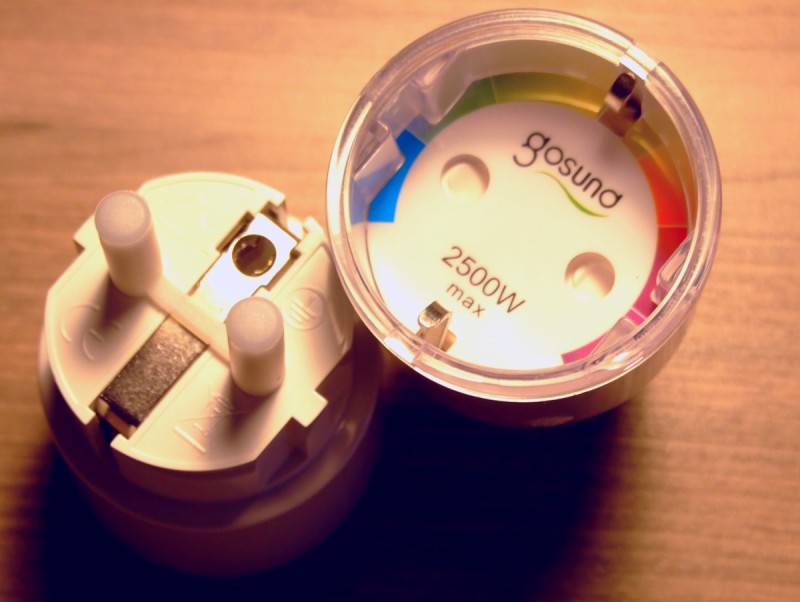
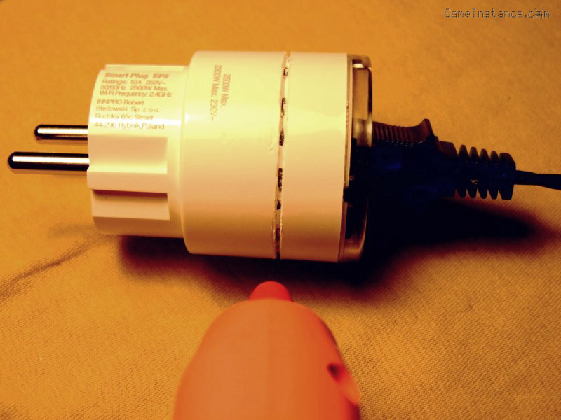
The subject of today's story is the Gosund EP2, often re-branded, which is based on the ESP8285 micro-controller. It's a very slim and slick design and it incorporates all security features one could think of. However, it is pre-programmed with a proprietary firmware and there's no telling what that may do besides what's expected of it.
Tasmota firmware
Is one open-source alternative and the best to this day. It can either be downloaded directly or built from the sources. You can do both starting from Tasmota github page but I recommend building the binary yourself. To achieve the latter with minimum fuss, one may use the pre-cooked building Docker image. The firmware can then be flashed using the esptool.py tool (to install it: sudo pip install esptool ).
Tools
- basic multimeter,
- fine saw (the finer, the better),
- flat screw-driver,
- long-shaft narrow-head Philips screw-driver,
- generic electrical pliers,
- fine-tip soldering iron,
- USB-serial adapter running at 3.3V (eg. FTDI FT232),
- wires,
- hot glue gun.
Disassembly
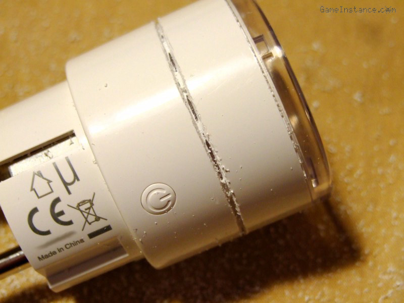
- Draw a cutting line around the plug, 17mm from the top. The cut must be made just above the socket's bottom.
- Initialize the cutting line with the saw blade. The purpose of this step is to obtain a continuous cut line around the socket.
- Carefully cut around the socket while observing the depth of the cut and the color of the plastic. After approx. 2 mm one should reach the transparent plastic. Do not go any deeper than this. Also, try to achieve an alternating pattern (white/transparent) so that once reassembled, the two pieces will remain at the same distance and allow the hot glue to fill the gaps correctly.
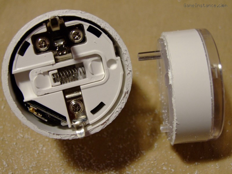
- Gently pry-open the two pieces using the flat head screw-driver. Clean the plastic filings from and around the two detached pieces.
- Remove the spring activated baby-proof protection. Don't forget to put it back when reassembling it!
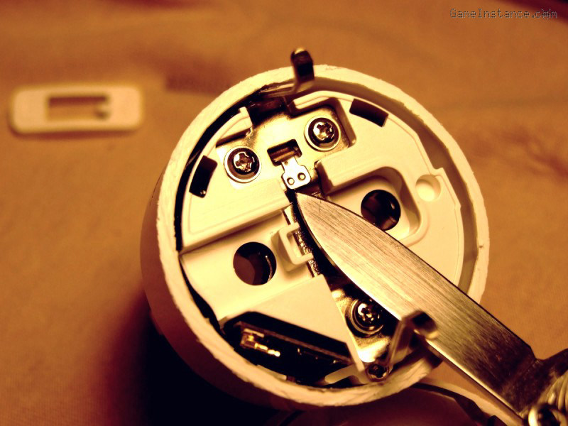
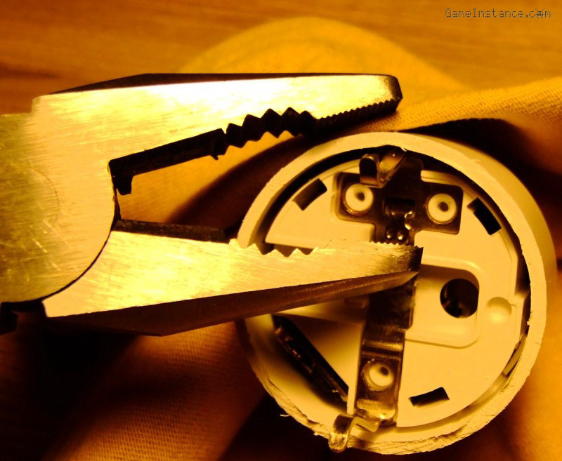
- Identify the contact welding between the two grounding pieces. Snap them apart with the pliers.
- Unscrew the 3 Phillips screws holding the top grounding piece, then remove it.
- Unscrew the 2 Phillips screws holding the smart-plug's circuitry assembly. Remove it by pushing onto the plug's pins.
Flashing
- Identify the connection points on the ESP8285 board: Vcc (3.3V), GND, Rx and Tx. Solder wires onto each of these. Connect them accordingly to the serial adapter. Remember to connect the Rx of the ESP to serial's Tx (same for Tx to Rx), otherwise the two parties won't be able to communicate.
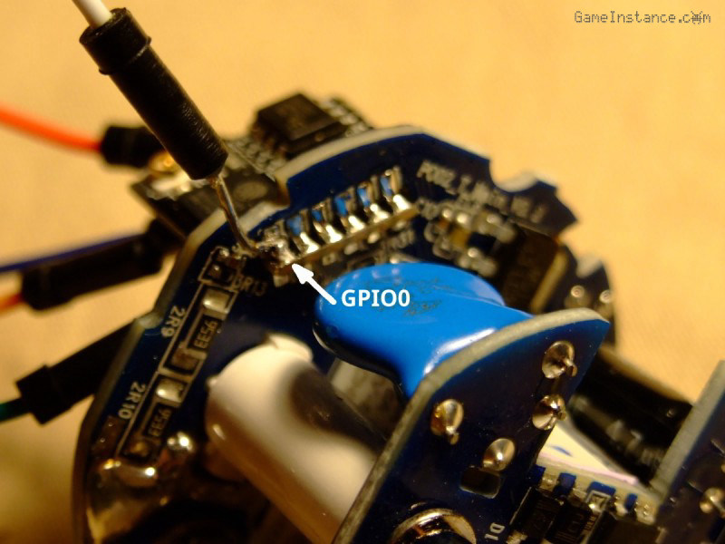
Solder another wire onto the GPIO0 pin. This will be used for booting the ESP in flashing mode.
- While holding the GPIO0 pin to GND, connect the USB-serial device to your computer. A blue LED indication will confirm this. You can now download the old firmware (optional), clean the flash and then write the Tasmota firmware. Assuming UART is allocated to ttyUSB0, execute the following:
# esptool.py --port /dev/ttyUSB0 read_flash 0x00000 0x100000 original.bin
# esptool.py --port /dev/ttyUSB0 erase_flash
# esptool.py --port /dev/ttyUSB0 write_flash -fs 1MB -fm dout 0x0 tasmota.bin
- At this point the firmware knows nothing about your WiFi infrastructure. It will create a temporary, time-limited and open WiFi network named tasmota-xxxxxx-yyyy. Connect to it with your PC or phone and access http://192.168.4.1/ . On this initial page, type the SSID and password of your local WiFi network, then save the config.
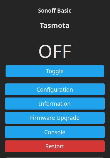
- From within your WiFi network, connect to your newly converted Tasmota device (using the IP assigned by your DHCP server), and configure its capabilities. Remember that Tasmota is a generic firmware and needs to be tweaked for each device. From the web interface, navigate to: Configuration -> Configure Other. Paste the following in the Template input:
{"NAME":"Gosund EP2","GPIO":[56,255,158,255,132,134,0,0,131,17,0,21,0],"FLAG":0,"BASE":45}
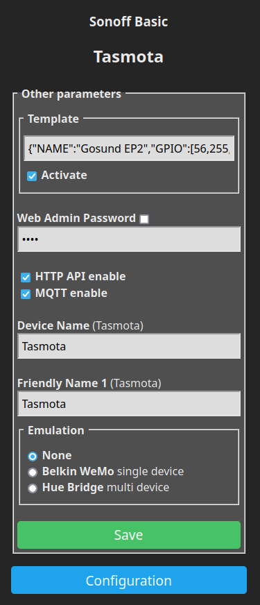
One could fiddle with the configurations further more but that's outside the scope of this guide. Setting the admin password for the new Tasmota device would be a good idea. In case some other device in your WiFi network goes rogue, it won't be able to toggle your smart-plug's switch or mess with its configuration.
Re-assembly and calibration
With the basic configuration in place, proceed with de-soldering the jump-wires and the reassembly of the smart-plug in reverse order, from step 8 to 4 (see above). When mounting the grounding pieces, use the elasticity of the bottom piece to achieve an electrical contact with the top one. Soldering the pieces is practically impossible due to the heat sinking ability of the large metal pieces. That said, the elastic force of the bottom piece is largely sufficient for a strong electrical contact. However, do check the resistance of that contact using a multi-meter; do not continue until you're reached a very low value between the two. Also, do not connect the plug to the mains before putting it back in its case!
Before gluing back the two pieces, check you haven't forgot something (screws, contact protection, etc). Use the hot-glue gun to carefully inject molten plastic continuously in the saw crevice around the plug. Insert a plug in the socket beforehand so that the top piece is held firmly in place for the success of this step.
To calibrate the voltage, one needs to use a multi-meter set on AC and for the power meter one needs a purely passive load with a know power, like a classic bulb (if you still have some). For details on how to do it, follow Tasmota's power monitoring calibration guide.
Safety net
It may happen that the few minutes time window for WiFi configuring expires or that you've messed up your connection credentials. All is not lost as there's a Tasmota recovery procedure for those situations.
The end.