While troubleshooting the current drive issue, I found the coil of the headphones output relay to be busted. Although not crucial and, in spite rarely listening to headphones, it too needed fixing. This wouldn't be as simple as buying and replacing it because the part is no longer in production. This article covers some reverse engineering, coil impedance adaptation, PCB design and building an equivalent THT part using SMD components.
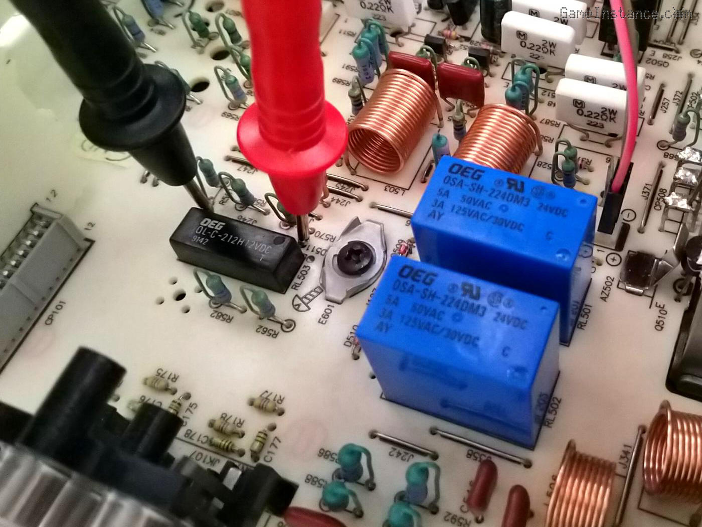 Technics SU-VX920 - headphones output relay, RL503 - in-circuit testing
First things first, I had to de-solder the relay for testing because checking the coil in-circuit, around other passive components wasn't conclusive, especially when there's no information about the part itself. And, indeed, the relay coil had infinite resistance.
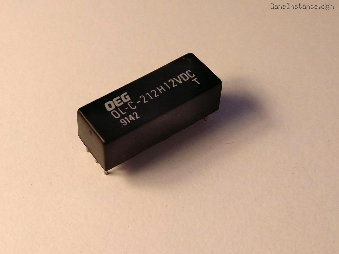 Technics SU-VX920 - headphones output relay, RL503 - removed from the main PCB
Searching information about this relay led nowhere. By now I was no longer surprised ... to have surprises. I was getting the hang of it. The low case profile made me think it was a reed relay and that made sense as headphones don't generally draw too much current.
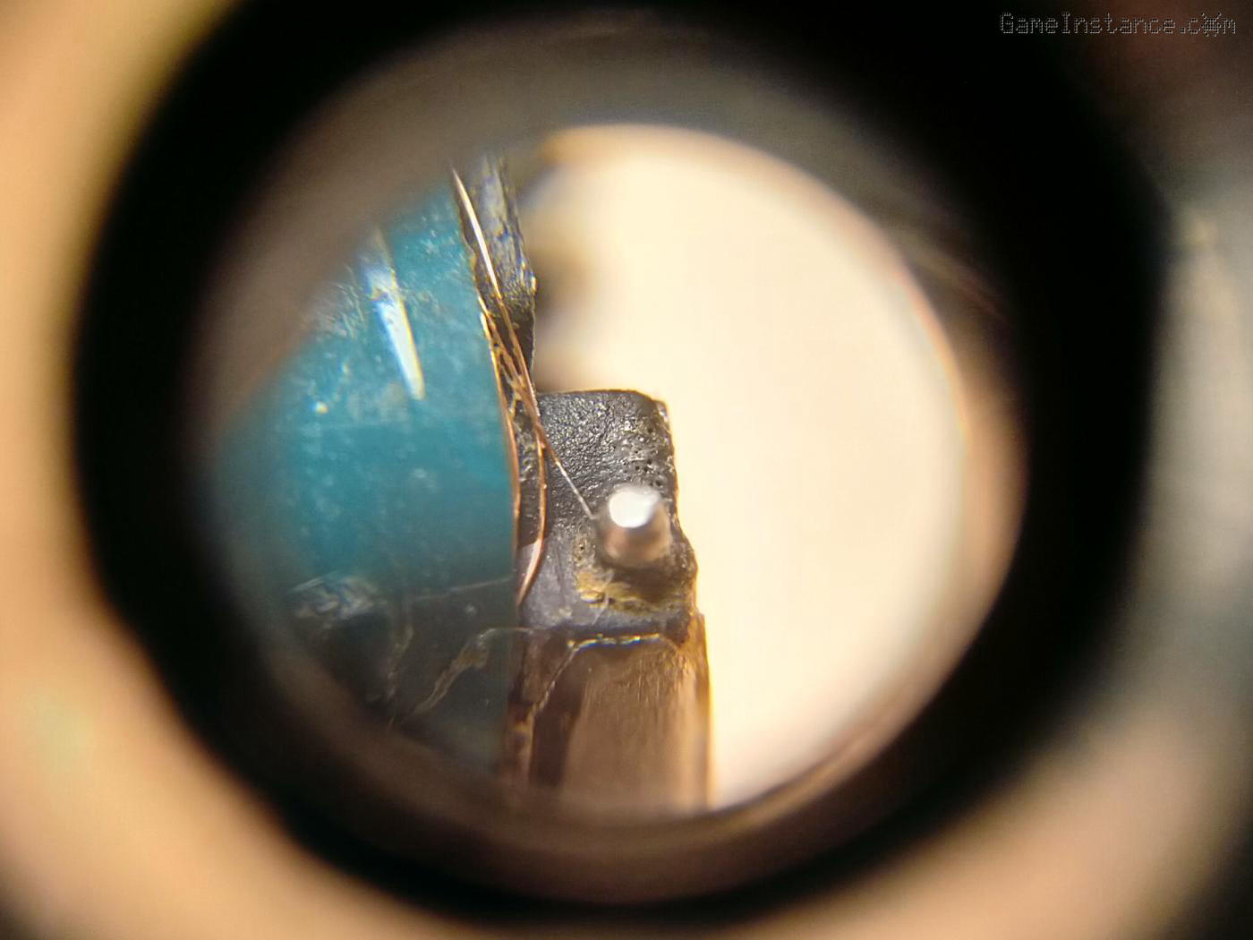 Technics SU-VX920 - headphones output relay, RL503 - no visible wire interruption
Hoping I'd find one of the wire ends snapped-off the package terminals, I dismantled the outer case of the relay. No luck: there's no visible/repairable interruption near the pins.
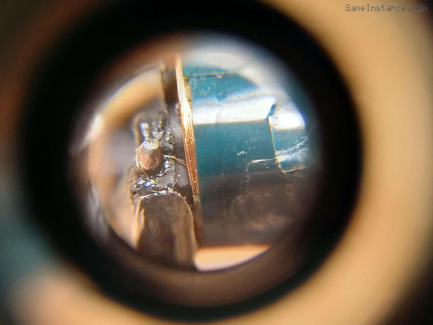 Technics SU-VX920 - headphones output relay, RL503 - no interruption at the other end either
I haven't heard anyone to be re-winding relays and surely I wasn't going to be one. All I needed to do was to find an equivalent and replace the old one. The relay isn't available anymore but that's not the biggest problem. The package itself seems to be obsolete or exotic. I just couldn't find any relays with that pin layout which meant I was forced to do some adaptation work. Great!
Before any adaptation could be done, I had to figure out the maximum voltage and impedance of the coil. Without a datasheet for this part and no hints in the amp's service manual either, I needed to do some reverse engineering. The labeling suggested it might be a 12V relay and with the circuitry around it reduced to the essentials, I was able to infer the following:
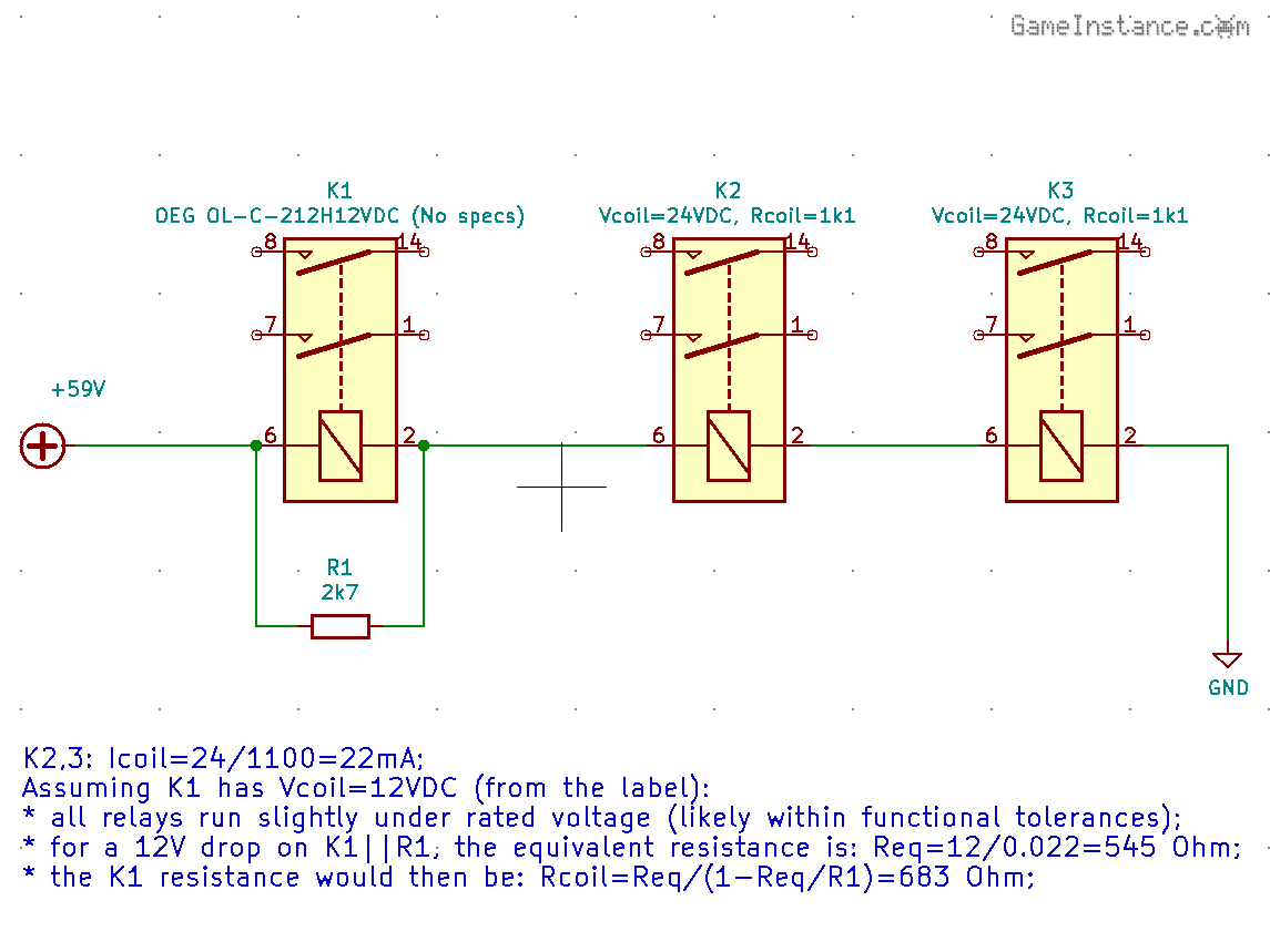
So, a 12V and 680-700 Ohm resistance DPST relay was what I was after. Any package that is small enough should do. From the start, I eliminated THT options because it would have led to a crappy wiring job. I was actually thinking of producing a small PCB with pins following the original relay's footprint, large enough to accommodate the new SMD relay, yet slim enough to fit around other parts on the amplifier's main board.
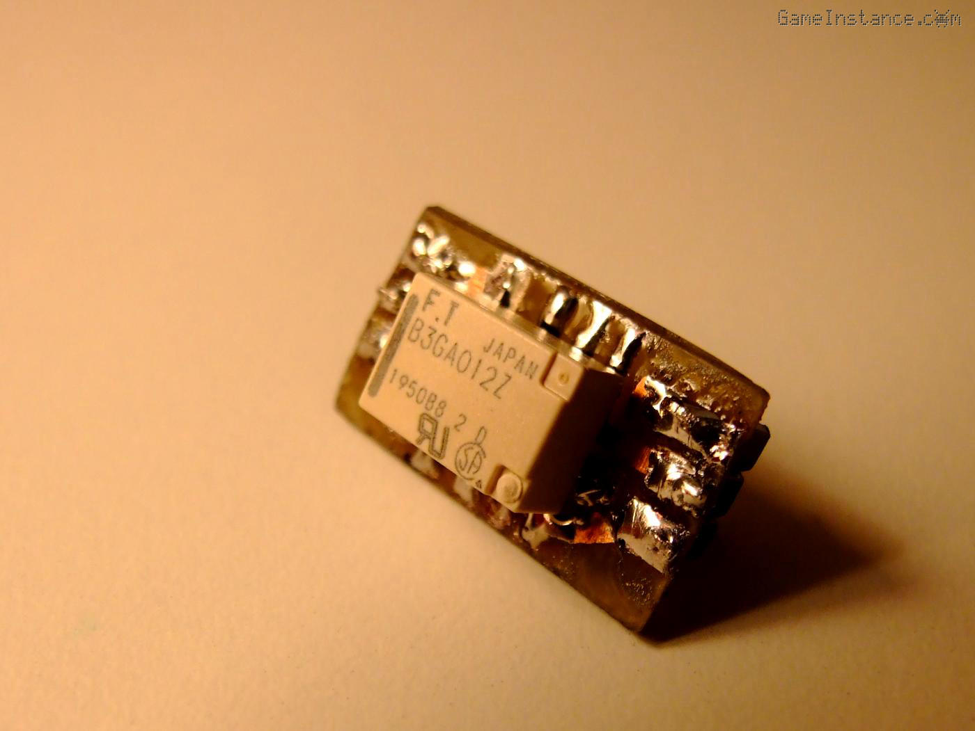
A candidate approaching these characteristics is the FTR-B3GA012Z. It is very small and has a contact rating of 1 amp. It has a 12V coil which is dissipating 140mW, meaning it has a resistance of 1029 Ohm. That isn't a big problem as the amp's PCB has a resistor in parallel with the relay, which give plenty of options. However, I wasn't considering changing the original design of the amplifier. If I have the opportunity to make an adaptation after-all, I might as well do it such that no modification to the host would be needed. The tiny board could have another resistor in parallel with the coil such that the overall impedance seen in the system approaches required 700 Ohm.
One KiCad hour later, I had the PCB layout ready for production. As a side note, I hate my PCB production process because it is just too convoluted for simple designs and almost never yields consistent results. My method of choice nowadays is toner transfer, which gives a decent etch mask but not always and not for small boards such as this one.
 Technics SU-VX920 - headphones output relay, RL503 - adaptation PCB layout (top, bottom)
 Technics SU-VX920 - headphones output relay, RL503 - adaptation device using a FTR-B3GA012Z
Once again, I ended-up manually correcting the etch mask and the result, well, isn't going to win any contest, to say the least. I actually see, past the implementation, the beauty in such adaptations. As for anyone else, they won't notice it hidden inside the amp's case.
 Technics SU-VX920 - headphones output relay, RL503 - adaptation mounted in place on main PCB
With the new adaptation in place, I could now hear the discreet relay click moments after the amplifier is powered on. The headphones output jack is now fully functional and, for the first time, I made a quick audition without adjusting the unit and still using the current-controlled power supply.
As I was planning for re-assembly while listening to my favorite tunes on the repaired headphones output, all of the sudden a grinding noise over-imposed on the left channel signal. It appeared out of thin air while turning-up the volume.
Check out how I troubleshot that one in Technics SU-VX920 repair - 3rd-part.