Few days have passed since my Technics SU-VX920 is running again and I'm delighted. This thing is a monster and I didn't push it beyond half its capabilities fearing it might burn through my Classix II's coils and crossovers ... or weaken the structure of the building I live in! It is transparent and clean, even at high output levels. Heck, that's what you get from two transformers, huge x-pro caps and two pairs of complementary transistors per channel.
I absolutely love it!
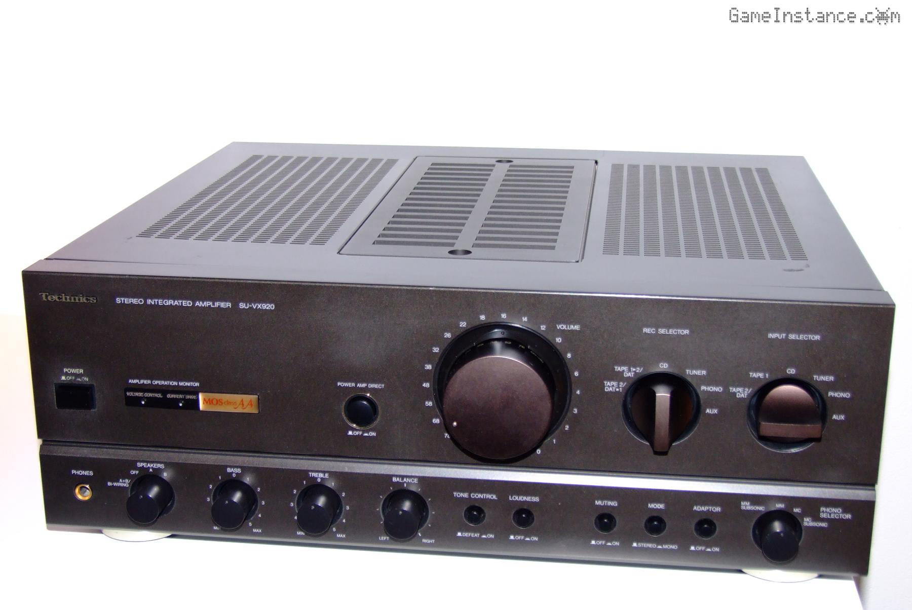
Having replaced the dodgy transistor on the voltage amp circuit, it was time for reassembly so I went ahead and tested everything. I checked every input, connector and even the recording outputs to discover one that wasn't working. Coincidentally, I also found another lifted, yet still connected, resistor pad on the operation PCB which was part of the problem but not the cause of it.
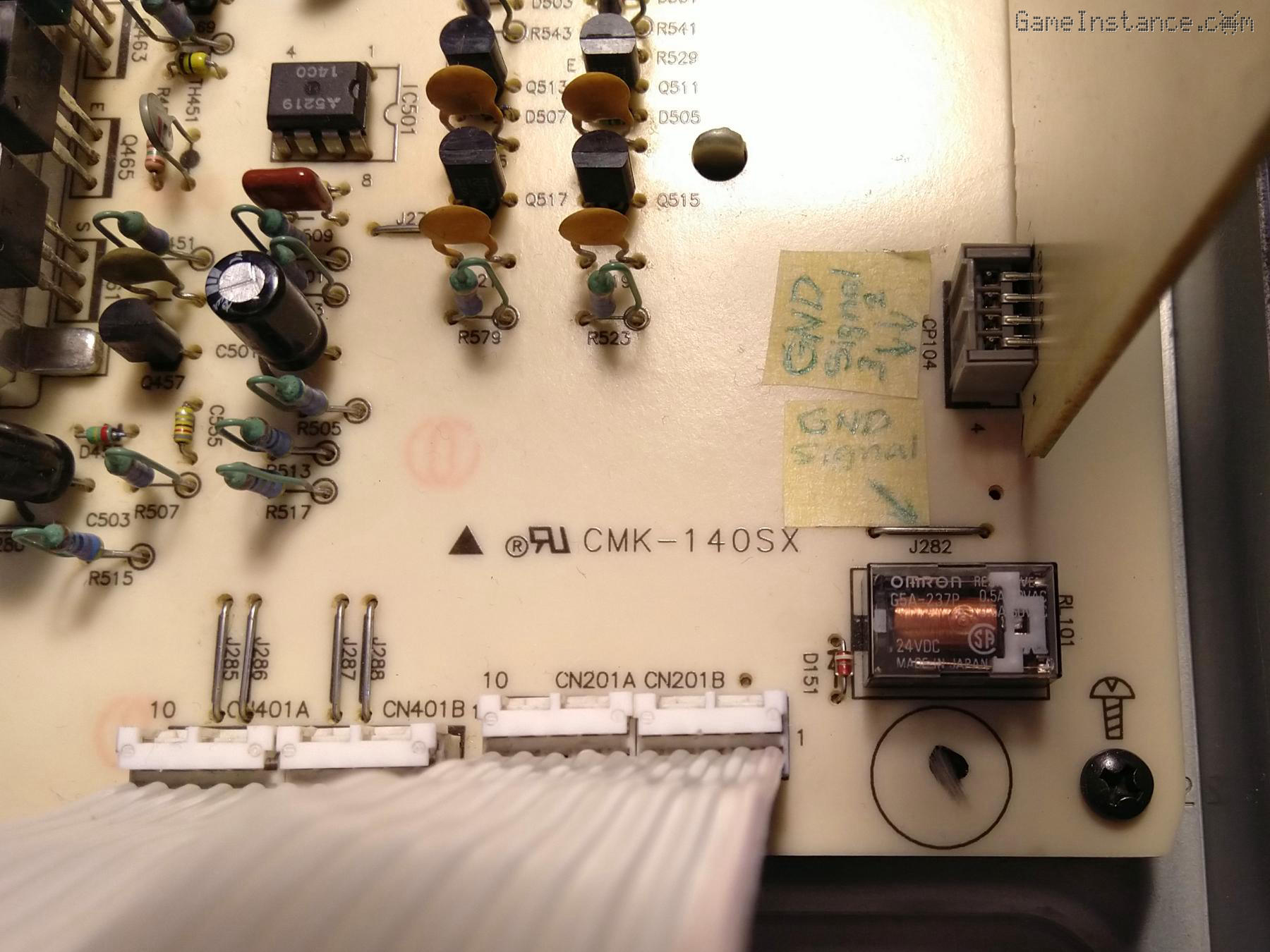 Technics SU-VX920 - ADAPTOR input relay on main PCB
The ADAPTOR input was not engaging by pressing the corresponding button on the front panel and with the help of the service manual I could isolate the problem to yet another relay, RL101. On a personal note, I find interesting how Technics engineers made the effort to control the interference on the high impedance lines by using rotary selectors mechanically connected via a flat cable to the actual multi-switch on the input PCB and then slam a relay actioned switch just after it. Anyway, I'm sure that made sense for them. So, by default that DPDT relay is connecting the amplifier input to the input selector's output, so to speak. If you press the button, the relay engages a shorter input path with RCA connectors mounted directly on the main PCB. I say interesting because there's also a DIRECT input that bypasses everything except the volume button, which is switched manually on the operation board. However, the latter is not as short as the ADAPTOR, spanning across multiple PCBs. This whole design seems kinda hackish.
When energized, the relay made a short fuzz but wasn't switching. Being fed through a ribbon cable from the operation board, it was easy to test in isolation and, as I initially guessed, it wasn't busted. I checked the circuitry supporting it but nothing was bad. Weird! I flipped the main PCB to check the traces and there were no problems there either, except for the visible traces of soldering on the relay pins. Hmm! I checked-out the reference for the RL101: it's an RSYG5A237P12. A quick search suggested it to be in fact an OMRON G5A-237P of 12VDC. Ok, I then tried feeding it 12V directly and same thing happened: a discreet fuzz and nothing else. Extraordinary! Yet another ghost problem, I said to myself even though I didn't believe in such nonsense.
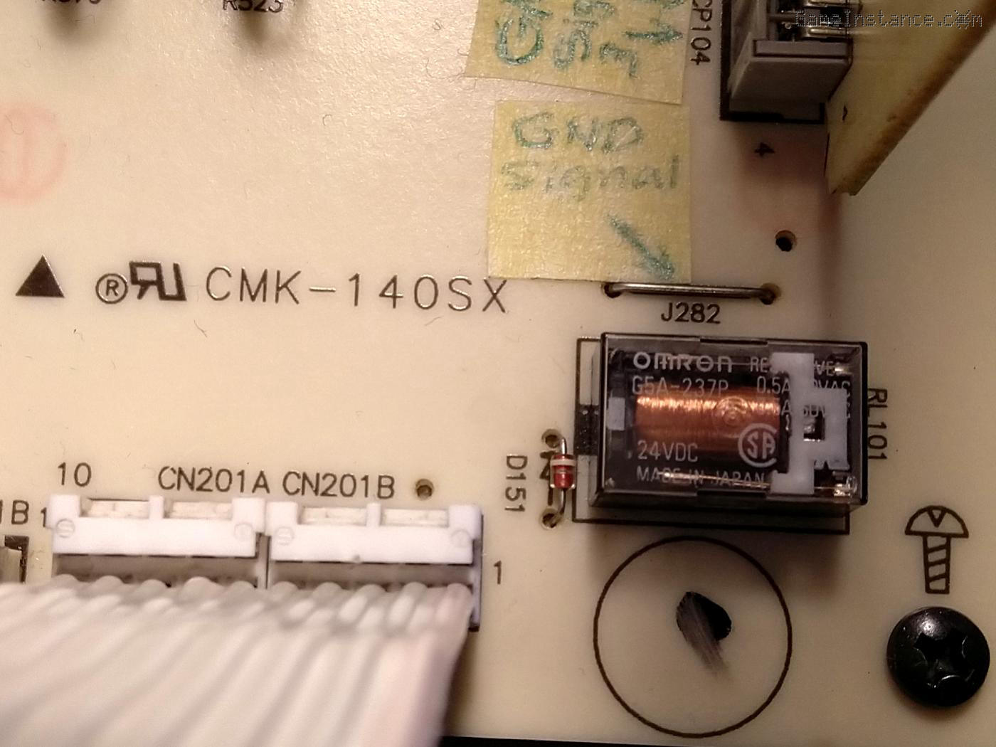 Technics SU-VX920 - ADAPTOR input relay with the wrong voltage rating
My error in this case was to take this unit for granted, as if it was new and not tampered with. It turned out that the relay installed was in fact a 24V one! Why? Don't ask me. I was the one inheriting it, with all its weirdness. Surely it didn't roll-out like that from the factory; such high-end amps would have been subjected at least to functional testing before going into the wild. Eliminating any possible error in the service manual reference, the power lines reaching the relay coil have a MA4120 12V zener diode in parallel and, of course, two 1W current limiting resistor before it. There's also a debouncing RC filter after the button but that's a geeky observation and totally off point. The problem is that the installed part isn't according to the design and specs.
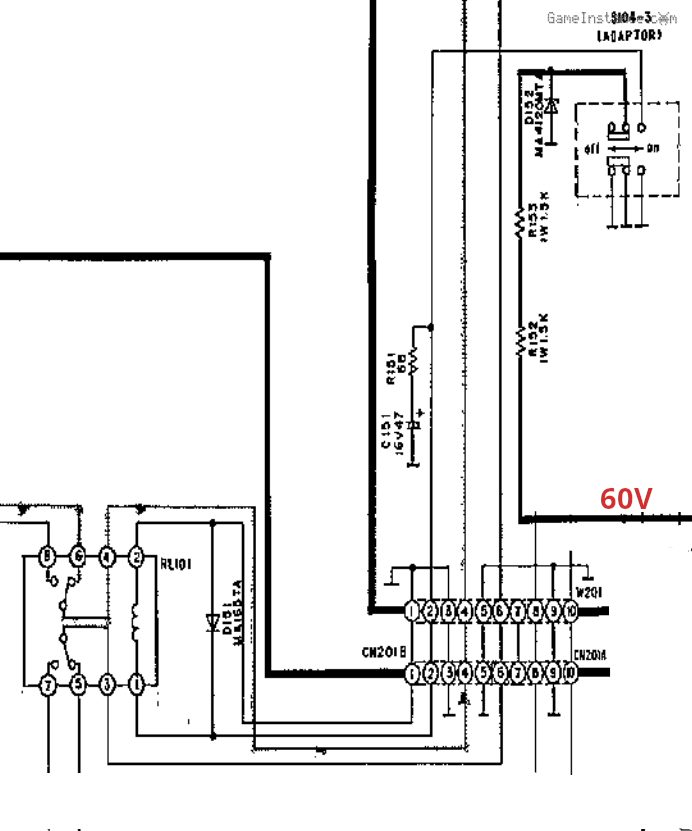 Technics SU-VX920 - ADAPTOR input relay and the front panel switch
My best guess is that whoever replaced it either had no clue or, worse, did it on purpose. Now, for the sake of exercise, imagine having a possessed amplifier sitting in your shop. One that for some unexplained reason nobody can fix and that's just taunting you with its presence. Say, another amp is being brought into the shop that needs a 12V relay and all you have are 24V. Conscience be damned, you use the 12V one from the haunted amp and swap it with a 24V. Salvage another unit with the hopes that some day, maybe, you'd buy 12V OMRONs and put one back to this god forsaken SU-VX920 to avoid having to explain the owner the missing relay, again, if ever. Sounds plausible, right?
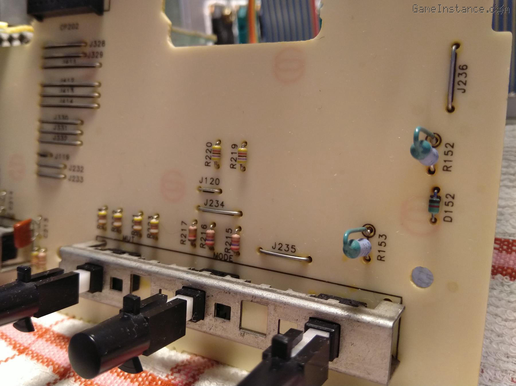 Technics SU-VX920 - ADAPTOR button, current limiting resistors R152 + R153, zener D152 on operation PCB
Anyway, having no such relay laying around neither and just aching to reassemble this amp, I chose to adapt to the situation myself. I replaced the zener with a 24V one without touching anything else. The limiting resistors were dissipating less than originally, yet providing enough current to toggle the 24V relay. For once, this was a clean and quick fix!
Check-out also the review of Technics SU-VX920.