Much has been said about Arduino and MCUs but there has been no mention whatsoever about the SPI communication. Too hacky for the entry-level Arduino hobbyist? So trivial that flew by below my radar? Yes, no, maybe. No matter the reason, now is as good as ever to mention it.
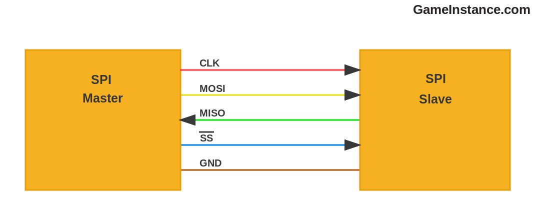
 Basic SPI setup; observe the presence of the common GND point
The SPI meaning and function is detailed on Wikipedia. You should take a good look there but if you find it too technical, you can always follow the rich variety of applications available online, courtesy of the DIY community. If you make no sense of any of those sources, ahem.
When to use SPI?
is what Wikipedia omits and I'm gonna try answering, so fingers crossed.
An SPI transaction can take place between two or more close-by sub-systems having SPI capability.
Why sub-systems and not just systems? Well, because of some limitations that will be discussed later in this article, the communicating chips need to be near to one another, hence the close-by, and preferably in the same screened box, usually sheltering a system. Each MCU or CPU would then be a sub-system.
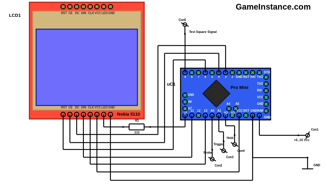
Consider a system that acquires some data, processes and displays it, such as ArduScope. Inside there's the ATmega 328 that does everything and the Philips PCD8544 that displays the wave.
 ArduScope - SPI master to mute slave communication example
This is the simplest example possible: ATmega as a master taking no feedback. Observe the MOSI pin 11 that goes to DIN on the display board and the absence of a MISO connection.
Remember that
Unlike GPIOs for instance, the SPI is capable of transmitting and receiving simultaneously bits of data at the MCU's frequency. The only bottleneck here is the slowest device involved in the communication. It should therefore be obvious that uC1 having 16MHz cannot communicate with the LCD1 supporting up to 4MHz unless the first scales down at least four times the CLK signal frequency.
Although not used in the above example, the SPI provides full duplex communication. That means data bits can travel both ways at the same time.
Worth specifying is the fact that SPI involves a well structured hierarchy. On the same SPI bus, multiple masters and slaves can coexist. While communicating however, there can only be one active master and one active slave that talks back. More active slaves can listen on the bus but need be silent.
Communication with each slave is controlled by the master through a set of dedicated SSx (slave select X) pins. When SS1 is pulled to GND, the slave #1 is activated for SPI communication with the master.
More of a blessing than a curse is the synchronous nature of the SPI communication. That means a clock signal generated by the master should be clearly visible to the active slave. The slave, in turn, should listen and respond to the master in the same temporized manner.
Limitations
Yeap, we got those too. Hardware-wise, long distances seem to affect SPI communication. Why? For two reasons: parasitic inductance and propagation delay, in that order. Both become problematic for high clock frequencies.
As the name suggests, parasitic inductance is a bad thing. It is specific to every wire and grows linearly with its length. The more inductance on the clock wire the bigger the signal distortion. Combined with a hint of parallel parasitic capacitance, it gives birth to a low-pass filter through which the clock square wave passes. The slave may get perplexed by the result signal or react later that expected by the master. Then there's the propagation delay that has to do with the speed of light scaled by the propagation medium coefficients but you know all that, don't you? If not, here's a little reminder.
All in all the SPI provides high speed transactional communication between sub-system devices grouped in well defined hierarchies. It uses just few connections to achieve the synchronous serial communication, two in the example above and excluding the common GND point, needs clock frequency adaptation with the slowest device in the group and connecting wires/traces need not stretch for more than few inches.