If a voltmeter measures average values at most, the oscilloscope goes beyond that and reveals the shape, amplitude and frequency of a signal, it helps determine capacitor and inductor values. Everyone who's someone has one and the rest want one. It is a nice toy but prohibitively expensive, even today and even the older models, so it's worth the effort to DIY.
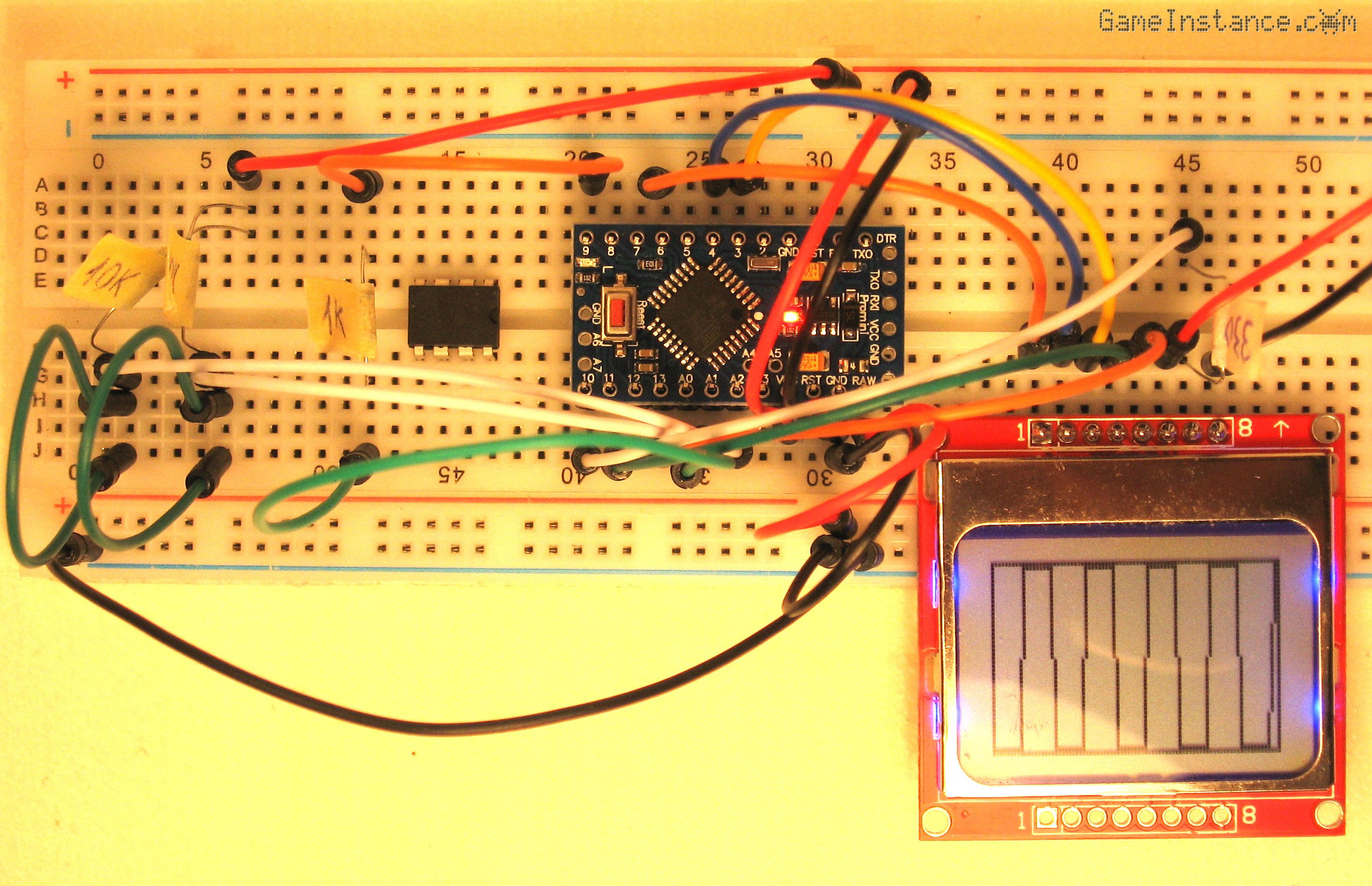 Arduino Oscilloscope - breadboard setup
This was too good of an opportunity to be missed. The ATMEGA328 has a couple of analog inputs with a decent resolution, more than enough for this application. On the downside, the analog-digital converter takes only positive input voltages and the sampling rate is rather mediocre for an oscilloscope. With its small resolution, the Nokia 5110 LCD is way out of its league as well. This will be a sub-par oscilloscope but mind you it will come handy.
The hardware
is basically identical to the Snake game setup. It has the same display connections and the same two buttons. For testing purposes, the Arduino digital pin 9 is generating a 490 Hz square signal with a 50 percent duty cycle between 0 and 5 volts. On future versions this will be used for calibration.
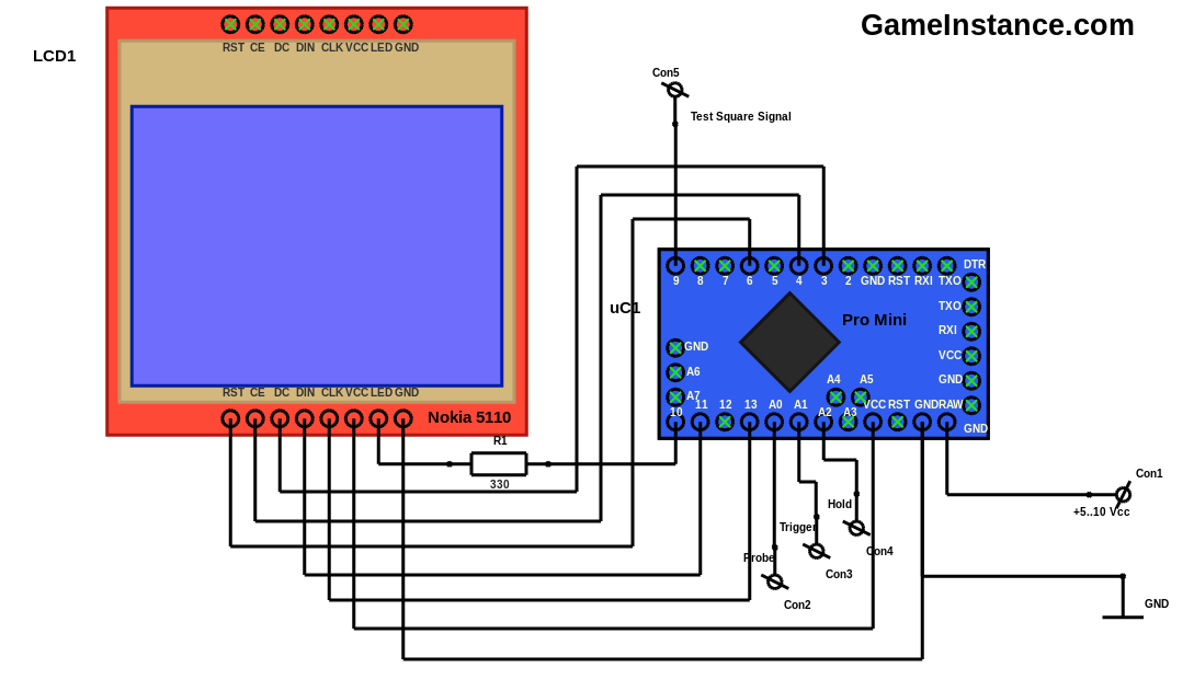 Arduino Oscilloscope - schematics
Bill Of Materials:
uC1 - Arduino Pro Mini or a clone
LCD1 - Nokia 5110 LCD or equivalent
R1 - 330 Ohm
R2,3 - 2x 10 kOhm
SW1,2 - 2x SPST Normally Open Switch
Oscilloscope probe (optional)
Breadboard
Jumper Wires
The software
relies on a simple automate that passes through trigger, acquisition and display states. The trigger state keeps the machine waiting for the selected event to take place. There are three trigger modes: none for no trigger, rising edge and falling edge. As their name suggests, the last two synchronize the acquisition of the signal with its passage upwards or downwards through the middle of the ADC's input range of 2.5 volts. The acquisition step fills a vector that gets displayed at the display state.
/*
 * Oscilloscope for Arduino
 * using the Nokia 5110 LCD
 *
 *  GameInstance.com
 *  2016
 */

#include <SPI.h>
#include <LCDNokia5100.h>

/// the display width in pixels
static const byte WIDTH = 84;
/// the display height in pixels
static const byte HEIGHT = 48;
/// sampling buffer size
static const unsigned int MAX_SIZE = WIDTH;

/// ADC resolution
static const int ADC_RESOLUTION = 1024;
/// ADC half resolution
static const int ADC_RESOLUTION_HALF = 512;
/// the line input
static const int INPUT_LINE = A0;
/// the trigger select button input
static const int INPUT_BUTTON_TRIGGER = A1;
/// the hold button input
static const int INPUT_BUTTON_HOLD = A2;
/// the test signal output pin
static const int OUTPUT_TEST_PIN = 9;

/// the state of the automate
byte state, trigger;
/// the display
LCDNokia5100 lcd;
/// values
unsigned int value[MAX_SIZE], currentSample, oldSample, triggerCount;
/// auxiliary values
byte currentValue, oldValue;
/// the buttons state
bool bPress[2], bHold;

/// indicates once that the button was pressed
bool wasPressed(int pin, int index, int threshold = 512) {
  //
  int val = analogRead(pin);
  //Serial.println(val);
  if (val > threshold) {
    // isn't pressed
    if (bPress[index]) {
      // but was before
      bPress[index] = false;
    }
    return false;
  }
  // is pressed
  if (!bPress[index]) {
    // and wasn't before
    bPress[index] = true;
    return true;
  }
  // but was before
  return false;
}

void setup() {
  // put your setup code here, to run once:
  //Serial.begin(9600);
  lcd.Start();
  lcd.Contrast(45);
  lcd.Light();
  lcd.Fill(false);
  lcd.Text("GameInstance", 8, 8, true);
  lcd.Text(".com", 30, 16, true);
  lcd.Text("DSO v0.1", 16, 32, true);
  lcd.Update();
  oldValue = 255;
  bPress[0] = false;
  bPress[1] = false;
  trigger = 0;
  bHold = 0;
  state = 0;
}

void loop() {
  // put your main code here, to run repeatedly:
  if (state == 0) {
    // splash
    delay(1000);
    analogWrite(OUTPUT_TEST_PIN, 127);
    oldSample = ADC_RESOLUTION + 1;
    state = 1;
  }

  if (state == 1) {
    // start
    triggerCount = 0;
    if (wasPressed(INPUT_BUTTON_HOLD, 1)) {
      // toggling the trigger mode
      bHold = !bHold;
    }
    if (!bHold) {
      // no hold
      state = 2;
    }
  }

  if (state == 2) {
    // triggering
    if (wasPressed(INPUT_BUTTON_TRIGGER, 0)) {
      // toggling the trigger mode
      trigger = (trigger + 1) % 3;
    }
    if (trigger == 0) {
      // no trigger
      state = 3;
    } else if (trigger == 1) {
      // rising edge trigger
      currentSample = analogRead(INPUT_LINE);
      if (oldSample <= ADC_RESOLUTION) {
        // not the first sample
        if ((currentSample >= oldSample)
          && (currentSample >= ADC_RESOLUTION_HALF)
          && (oldSample <= ADC_RESOLUTION_HALF)) {
          // event triggered
          state = 3;
        } else {
          // not yet triggered
          triggerCount ++;
          if (triggerCount == MAX_SIZE) {
            // inform user
            lcd.Fill(false);
            lcd.Text("Trigger wait", 8, 8, true);
            lcd.Text("rising edge", 8, 24, true);
            lcd.Update();
          }
        }
      }
      oldSample = currentSample;
    } else if (trigger == 2) {
      // falling edge trigger
      currentSample = analogRead(INPUT_LINE);
      if (oldSample <= ADC_RESOLUTION) {
        // not the first sample
        if ((currentSample <= oldSample)
          && (currentSample <= ADC_RESOLUTION_HALF)
          && (oldSample >= ADC_RESOLUTION_HALF)) {
          // event triggered
          state = 3;
        } else {
          // not yet triggered
          triggerCount ++;
          if (triggerCount == MAX_SIZE) {
            // inform user
            lcd.Fill(false);
            lcd.Text("Trigger wait", 8, 8, true);
            lcd.Text("falling edge", 8, 24, true);
            lcd.Update();
          }
        }
      }
      oldSample = currentSample;
    }
  }

  if (state == 3) {
    // acquisition
    for (byte i = 0; i < MAX_SIZE; i ++) {
      //
      value[i] = analogRead(INPUT_LINE);
    }
    state = 4;
  }

  if (state == 4) {
    // display
    lcd.Fill(false);
    lcd.Line(0, 0, WIDTH - 1, 0, true);
    lcd.Line(0, 0, 0, HEIGHT - 1, true);
    lcd.Line(WIDTH - 1, HEIGHT - 1, WIDTH - 1, 0, true);
    lcd.Line(WIDTH - 1, HEIGHT - 1, 0, HEIGHT - 1, true);
    for (byte i = 0; i < MAX_SIZE; i ++) {
      //
      currentValue = (byte)(HEIGHT - (value[i] * (HEIGHT - 2) / ADC_RESOLUTION) - 2);
      if ((oldValue == 255)
        || (i == 0)
        || (abs(currentValue - oldValue) <= 2)) {
        //
        lcd.Point(i, currentValue, true);
      } else {
        //
        lcd.Line(i - 1, oldValue, i, currentValue, true);
      }
      oldValue = currentValue;
    }
    lcd.Update();
    delay(100);
    state = 1;
  }
}
Check-out ArduScope on GitHub.
Functions
By default the oscilloscope uses no trigger. Using the first button, one can toggle the trigger modes with immediate results. However, if the signal doesn't meet the trigger condition, the program will wait indefinitely. The second button allows user to hold the image displayed on the screen. The probe can be connected to the test output and a square periodic signal will be displayed.
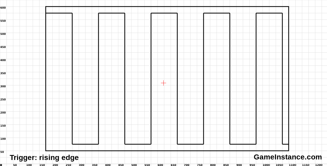 Arduino Oscilloscope - test square signal
Conclusion
As it is right now, the tool lacks a second input, an external trigger, a way of storing the displayed data and it doesn't have an input signal attenuation-amplification stage. These features can be added later on. It is also limited by the low sampling frequency of the 328 and this cannot be improved much. Better micro-controllers, external ADCs and FPGAs will be required to achieve that.
So stay tuned, we're in for more fun!
Update
You can find a beefier Digital Oscilloscope here. It was built on top of the STM32 MCU with sampling rate of up to 1MS/s and features a bigger color TFT display.