Few months back I posted the Digital Oscilloscope built on top of the popular ATmega328 and the Nokia 5510 LCD which was fairly limited in screen resolution and ADC conversion speed. Few weeks after that I compiled a short comparative presentation of the STM32F103C8, packed as Blue Pill, and indicated how to connect and program it. Its ADC showed promising features and so it became the next contender for the DSO update. Later on, up came the 2.4" TFT display powered by the NT35702 controller with it's 320x240 pixels and 16 bit colors. This article shows you how to use them to build your own simple Digital Oscilloscope with about 6 dollars worth of parts.
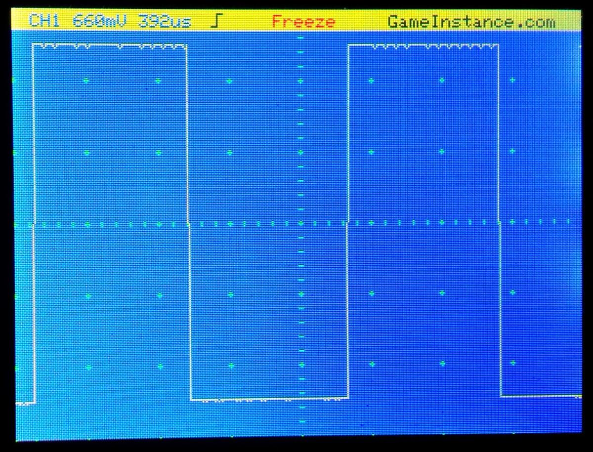 STM32 Digital Oscilloscope screenshot - displaying the self-test signal
In case you're wondering, here're some specs:
- One channel
- Up to 1 MS/s
- 512 bytes for signal recording
- 2.4" TFT color display
- Software triggers: raising edge, descending edge
Keep in mind that this is a very low cost DIY oscilloscope, meant for testing low frequency projects only.
The connections
are generally the same as those made in the previous post. You'll need to follow those instructions and then get back here. For simplicity, the DSO channels are connected directly to the analog inputs of the STM32. This means there's no attenuation-amplification circuit and that the input signal should not exceed 3.3 volts or drop below GND.
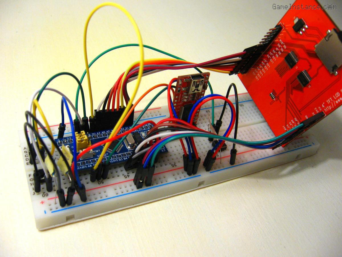 STM32 Digital Oscilloscope - breadboard setup
The novelty in this setup is the presence of three buttons for trigger, time divisions and screen freeze. The schematic below represents the circuitry for each of those buttons. The Button IN goes to the corresponding MCU input pin. The MCU pin attribution will change as updates and upgrades will be made to the project. For where each button goes, ALWAYS check the constant definitions in the code.
 STM32 Digital Oscilloscope - button circuit
As a means of self testing, the TEST_SIGNAL pin will permanently generate a 50% duty cycle PWM signal. You can connect the CHANNEL_1 input pin to it every now and then to see if it still works.
The code
relies on a state machine that monitors the analog inputs for trigger condition, acquires a set of data and then displays it. An additional state checks for pressed buttons. Note that no interrupt routines were used in this application. Reason being that the ISR execution could perturb the temporal equidistant data sampling. Another new functionality is the time base selection, see the TIME_BUTTON in the source code. Other than that, the code is pretty self-explanatory.
You can find it as STM32 Digital Oscilloscope on GitHub.
Far from it
This Oscilloscope is better than the previous one but nowhere near the big league specialized or entry level tools. It is however a starting point that can postpone that costly purchase. It can be used successfully for ATmega328 PWM projects, for debugging low frequency circuits or audio signals. It is a nice DIY tool that you'll also be doing yourself and have a lot of fan while at it. So enjoy it!
Update: Check-out the much improved version of the STM32 Oscilloscope.