I found myself numerous times in the awkward situation of opening the box of my irrigation system to hook the FTDI adapter onto the Arduino's serial port. Whether it was for debugging or for changing configurations, it was annoying and I wanted an alternative. Then I came across the inexpensive SPP-CA module that acts as a wireless extension of the serial communication. You have to bluetooth into it and it connects to the MCU. Simple, elegant, great!
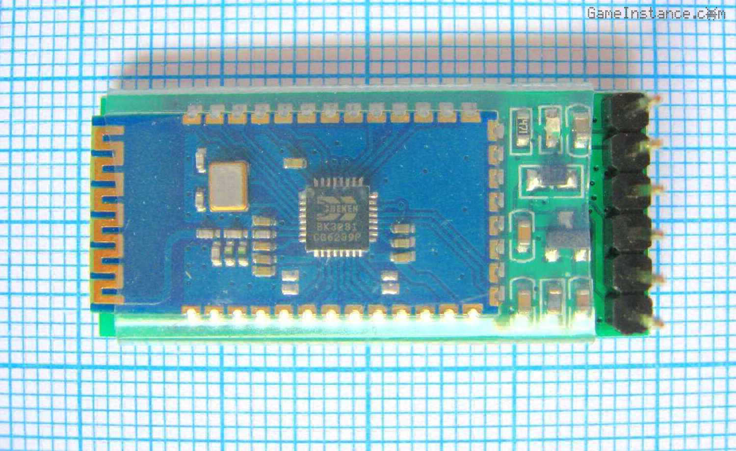 SPP-CA, a Class 2 Bluetooth 2.1 module with EDR - used for remote serial communication
The SPP-CA module is a 3.7 cm x 1.7 cm board with a 6 pin breakout connector. Besides the power pins, it has the TX and RX for UART serial communication. It also features a very handy output pin, the MCU-INT, that goes HIGH when the module gets connected. Thrown in the mix is also the CLEAR pin that does nothing useful, at least not in this application.
The module I got was made by Bolutek and its datasheet says it's a class 2 radio device. That means up to 10 meters of connection distance between the master and it, which is good enough. In fact I was aiming for less than 5 meters.
Caution:
Keep in mind that the module is powered and operates with 3.3 volts. If your Arduino board is too, just ignore the rest of this notice.
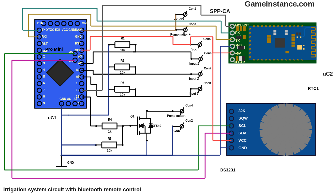
So, your Arduino MCU is powered by a 5 volts source. The SPP-CA breakout board has a voltage regulator serving the bluetooth chip, thus the power discrepancy fell off the table. The SPP-CA serial pins, on the other hand, are generating 3.3 volt outputs and are expecting 3.3 volt at the input. The output signal going into the Arduino is interpreted correctly. A 3.3 volts HIGH level is still HIGH for the 5 volts Arduino. However, the inputs should be passed through voltage dividers, to reduce the amplitude of the signal from 5 volts to 3.3 volts. Without the reduction either the Atmega's output or the bluetooth's input will risk getting fried.
Why does that happen? Well, almost all ICs have clamping diodes for input protection. Their purpose is to short-circuit anything outside the supported voltage to the power rail. The diodes are scaled for shorting small current signals only. As long as the signal generator sources a small current, the clamping diodes handle it. However, sourcing more than 10mA from a Atmega328p output will permanently damage it. A directly connected clamped input could do just that. Hence, a current limiting resistor placed between the two can mediate this arm-wrestling. Its resistance should be at least 170 Ohms = (5V - 3.3V) / 0.01A .
With the setup above I can remotely read serial output from the MCU on my Android phone. All I had to do was to install the Bluetooth Terminal app, start it and connect to the previously paired device. By default, the bluetooth board appears with the SPP-CA name.
Now what if I could also send commands that make configuration changes from my mobile phone while the sketch is running? That would mean I'd no longer need to connect to it via the FTDI adapter, rewrite the sketch with the new constants and then reboot it.
What an interesting thought!
Update: Check-out the outcome of this attempt.