Two weeks ago I played around with an SPP-CA bluetooth module and I found it great for dumping MCU serial output on my phone. It then came to me that remotely controlling the system parameters would be even better. I saw potential for an upgrade on my off-grid irrigation system and went for it. This article reflects what I came up with.
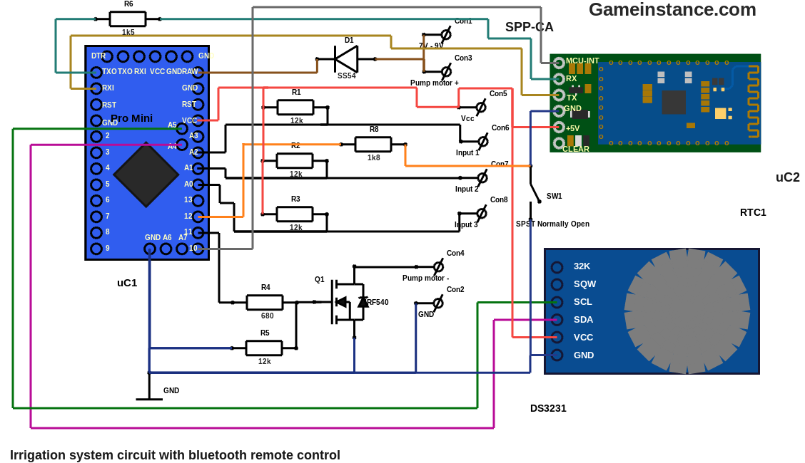
The major changes
in the schematic, compared to the original Arduino plant irrigator, are given by the accommodation of the SPP-CA module, bluetooth power and connection state signaling as well as the extra protection of the circuit components. Starting with the latter, the newly added D1 diode - an SS54 Schottky - offers a protection from yourself. Accidentally reversing polarity will certainly destroy the Arduino's voltage regulator so bear that in mind if you consider removing it.
The cascade-full and the tank-empty switches are now closing to GND. As a consequence the R1-3 are acting as pull-up resistors. This is to minimize the chances of an accidental short-circuit of the Vcc with the common GND. That can be possible when intermingling projects having both pulled-up and pulled-down sensors that are powered by the same source. You get the picture :)
 The irrigation system input switches pulled-up by 12 kOhm resistors and closing to GND.
The SPP-CA can be turned on and off through the SW4 switch. It may be continuously powered but it will draw a non-negligible current, even when not in use. Interrupting the Vcc won't do because the SPP-CA manages to sip-in some current from the Arduino's TX pin, just enough to keep it functioning. The only feasible way of turning it off using a single-pole switch is to cut its GND connection.
When powered off, the entire circuit goes HIGH as it stabilizes to Vcc potential. The internal resistance within the SPP-CA is sufficient to pull-up Arduino's sensing pin 12. Again, this indicates the MCU whether or not the SPP-CA is powered. When the SPP-CA is off, the MCU can get into low-power mode. The level information reaching pin 12 is passed through the 1.8 kOhm R8 resistor. In case pin 12 accidentally becomes an output stuck into HIGH state, simply pressing the bluetooth power button will destroy the Arduino.
Less major changes
You may be wondering why the 12 kOhm pull-up resistors. It has become a common practice to use 10 kOhm resistors for this purpose so you're entitled to ask. However, the role of the pull-up or pull-down resistor is to gently pull the connected line to the Vcc or GND rails. Unless time-to-rail restrictions are requested or current limits are imposed, any reasonable resistor value will do. As such, 12K ohm resistors will do just fine.
The R6 resistor limits the current drawn by the 3.3V SPP-CA RX input from the Arduino's 5V TX pin. As previously stated, the SPP-CA's input is protected by clamping diodes that short-circuit to the rail (3.3V in this case) anything above that. The 1.5 kOhm is more than enough. Bigger resistor values that will expose the SPP-CA's RX to lower SNR levels.
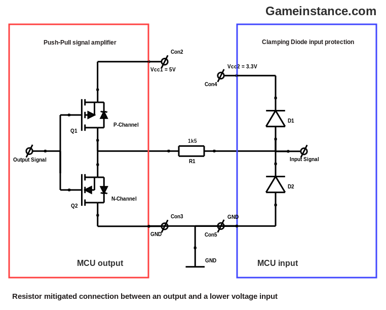
There used to be a R7 resistor that, together with the R6, performed voltage division for the SPP-CA's RX. That caused more problems that it solved. The R6 + R7 composition generated a pull-down resistor for the Arduino's TX pin that prevented the synchronization with the FTDI module when flashing sketches.
The approach
was a bit tricky. Since the old PCB could no longer be maintained - through hole parts mixed with wires on both sides of the board - I had to rebuild it. This is the previous version:
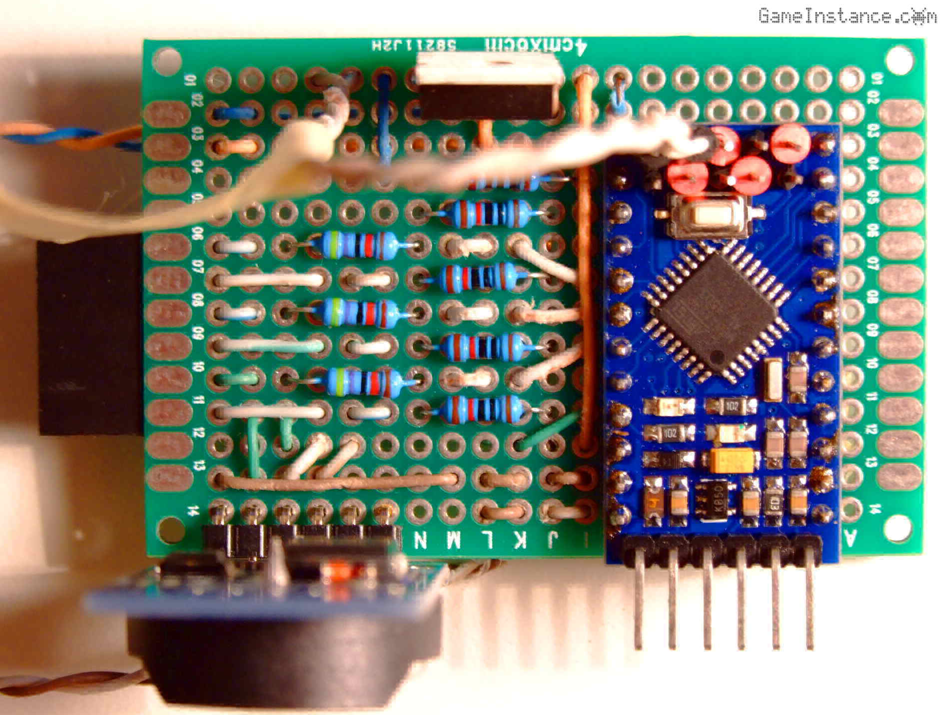 Irrigation system board - first draft. Observe the UV corrosion of the wire insulation after few weeks in a transparent box under the scourging summer sun.
The SPP-CA's header and the connections needed extra real-estate that wasn't available in the current configuration. I decided to drop the through-hole resistors in favor of the surface mount ones.
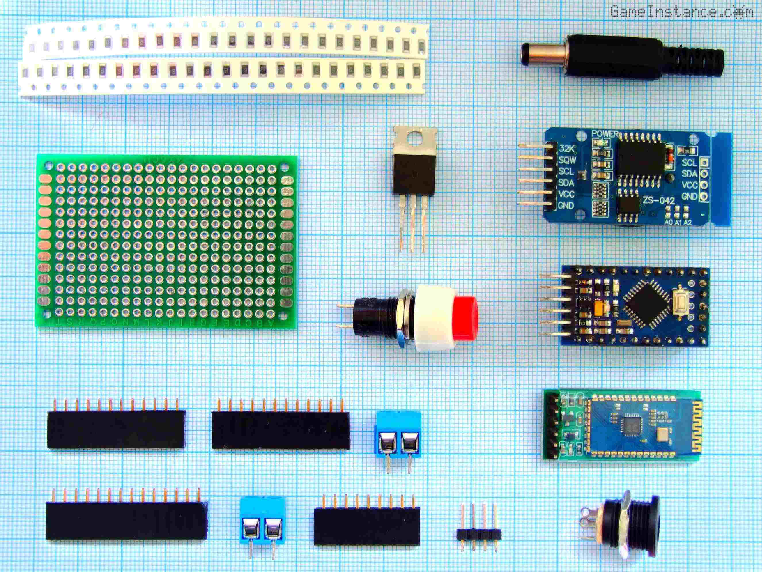 Off-grid irrigation system with bluetooth remote control - the component roundup
To get the maximum debugging flexibility at later stages, I opted for more female single-pin headers. Not only for connecting the sensing switches but also for consumables and generally through-hole components such as the MOSFET, Arduino Pro Mini, the RTC and SPP-CA modules. Consequently, this permits solderless part replacement whenever needed. My pump barely draws 200mA. The single-pin headers can easily handle that current.
Bill of materials
When you source parts from manufacturers and in large quantities, the list of charges won't surpass few dollars. Buying in small quantities gets you around five dollars for this project. Here it is:
BOM:
uC1 - 1x Arduino Pro Mini or a clone
uC2 - 1x SPP-CA bluetooth module
RTC1 - 1x DS3231 real-time clock module
Q1 - 1x IRF540 or IRF530 N-Channel MOSFET
R1-3,5 - 4x 12 kOhm SMD resistors
R4 - 1x 680 Ohm SMD resistor
R6 - 1x 1.5 kOhm SMD resistor
R8 - 1x 1.8 kOhm SMD resistor
1x PCB prototyping board 6cm x 4cm
Optional:
D1 - 1x SS54 Schottky diode
SW1 - 1x Single-pole switch, box mounted
Con1,2 - 1x Female power plug 2.1mm x 5.5mm, box mounted
The result
looks reasonable and most importantly, it works. Wiring the back of the board is going to be a pain but with patience and perseverance you'll get it done too. Do yourself a favor, use a helping hand tool and a pair of pliers or a pincer.
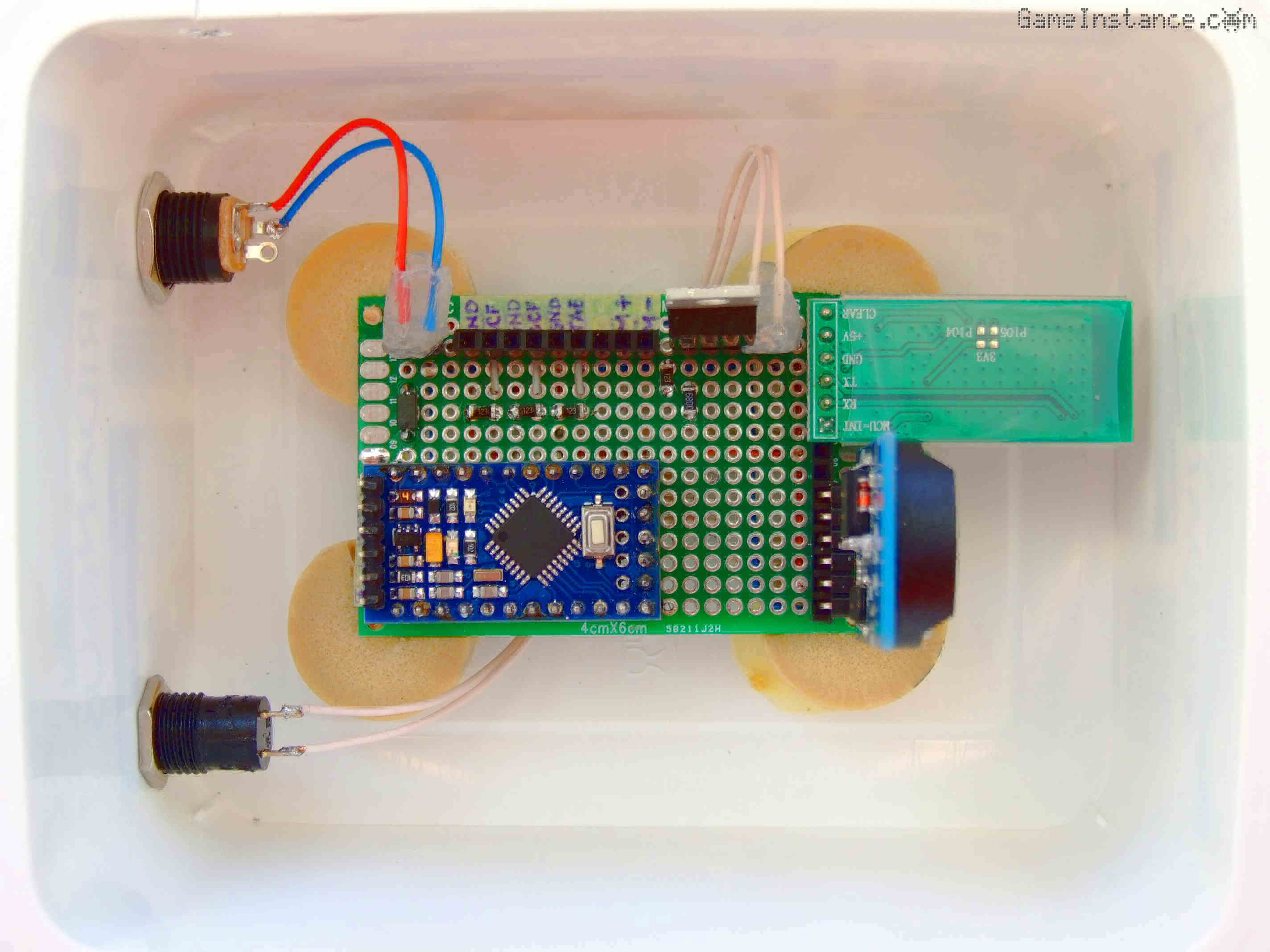 Off-grid irrigation system with bluetooth remote control - the PCB, the fixation mounts and the box
Among many other things, I like cheese and frizzantes! I enjoy them for their exquisite taste, refined aroma and the occasional tipsiness. They also leave behind handy stuff such as cork plugs, plug harnesses or plastic boxes. Being scrappy, I keep some of those for my DIY projects. For this one, I've scavenged a plastic feta cheese box - otherwise quite sturdy - for the system casing, cork plugs for PCB mounts and cork plug harness wires for various strappings.
Warning:
Using small currents and low voltages keeps you away from harm's way. However, if you're considering high power water pumps, do work by the code. Use fire retardant electric boxes, proper insulation, better PCB mounts, etc.
You may opt for a custom made case. At this stage in my project, I don't consider it essential. The cheese box serves the purpose just fine.
The software
has its starting point in the old sketch with changes for reading from serial, parsing commands and storing configurations. For the first two purposes I devised a generic abstract class called SerialCommand that needs to be extended/implemented for each particular application, in this case, MySerialCommand.
/*
 * The app specific serial command class.
 */
class MySerialCommand : public SerialCommand {

  public:

    /// default constructor
    MySerialCommand() : SerialCommand() {
      //
      pConfig = 0;
    };
    /// destructor
    virtual ~MySerialCommand() {
      //
    };

    /// sets the config object pointer
    void SetConf(MyConfig* pC) {
      //
      pConfig = pC;
    }

  protected:

    /// runs the command
    bool Run() {
      //
      switch (data[0]) {
        //
        case '?':
          // identify
          Identify();
          return true;
        case 'i':
          // store new config
          Parse();
          StorePeriod();
          return true;
        case 'h':
          // store new config
          Parse();
          StoreHour();
          return true;
        case 'd':
          // dump the FSM state
          return Dump();
      }
      // unknown command
      Serial.println("Unknown command!");
      return false;
    };
    /// identifies the app
    void Identify() {
      //
      Serial.println("Scheduled Off-Grid Irrigation System");
/*
      Serial.println("Commands:");
      Serial.println("? - help");
      Serial.println("d - dump config and machine state");
      Serial.println("i:X:Y:A:B - Sets the X=period, Y=start, A=alternating, B=small only");
      Serial.println("h:A:B:C:D - Sets the A=startHour, B=startMinute, C=endHour, D=endMinute");
*/
    };
    /// parses the command data
    bool Parse() {
      //
//      Serial.print("Command: ");
//      Serial.println(data);
      char s[64];
      byte j = 0, k = 0;
      for (byte i = 1; data[i] != '\0'; i ++) {
        //
        if (data[i] == ':') {
          // delimitor
          s[j] = '\0';
          var[k] = atoi(s);
          j = 0;
          k ++;
        } else {
          // acquire data
          s[j ++] = data[i];
        }
      }
      s[j] = '\0';
      var[k] = atoi(s);
    };
    /// stores the period data
    void StorePeriod() {
      //
      pConfig->SetPeriod(var);
      pConfig->SavePeriod();
      state = 0;
    };
    /// stores the hours
    void StoreHour() {
      //
      pConfig->SetHour(var);
      pConfig->SaveHour();
      state = 0;
    };
    /// dumps the FSM state
    bool Dump() {
      //
      trace("");
      Serial.println("--- FSM DUMP ---");
      Serial.print("FSM state: ");
      Serial.println(state);
      Serial.print("Debug mode: ");
      Serial.println(DEBUG ? "Yes" : "No");
      Serial.print("Today is day #: ");
      Serial.print(today(), DEC);
      Serial.println(".");
      pConfig->Dump();
      Serial.print("Tank empty: ");
      Serial.println(tankEmpty() ? "Yes" : "No");
      Serial.print("Big cascade full: ");
      Serial.println(bigCascadeFull() ? "Yes" : "No");
      Serial.print("Small cascade full: ");
      Serial.println(smallCascadeFull() ? "Yes" : "No");
      Serial.print("Bluetooth power: ");
      Serial.println(digitalRead(BLUETOOTH_POWER_PORT) ? "No" : "Yes");
      Serial.print("Bluetooth connection: ");
      Serial.println(digitalRead(BLUETOOTH_CONNECTION_PORT) ? "Yes" : "No");
      Serial.println("--- END OF FSM DUMP ---");
      return true;
    };

    /// a sixteen bytes config
    byte var[16];
    /// pointer to the config object
    MyConfig* pConfig;
};
The Parse method could have been placed in the base class but then that would have been less generic. The MySerialCommand refers to a configuration object called MyConfig. It has all the methods of setting, storing, loading data to and from EEPROM. Yes, the Atmega 328p has 1024 bytes of that too. Not much, I know, but enough for the problem at hand.
/*
 * The app specific configuration class.
 */
class MyConfig {

  public:

    /// default constructor
    MyConfig() {
      //
    };
    /// destructor
    virtual ~MyConfig() {
      //
    };

    /// loads interval data
    bool LoadInterval() {
      //
      byte value;
      // loading the irrigation period
      value = EEPROM.read(0);
      if ((value < 1) || (value > 10)) {
        // invalid value
//        Serial.println("Failed on irrigation period. ");
        return false;
      }
      irrigationPeriodDays = value;

      // loading the irrigation day
      value = EEPROM.read(1);
      if (value >= irrigationPeriodDays) {
        // invalid value
//        Serial.println("Failed on irrigation day. ");
        return false;
      }
      irrigationDay = value;

      // loading the cascade alternation flag
      cascadeAlternation = (bool) EEPROM.read(2);

      // loading the small cascade only flag
      smallCascadeOnly = (bool) EEPROM.read(3);

      return true;
    }
    /// loads the hour data
    bool LoadHour() {
      //
      byte value;
      // loading the begin hour
      value = EEPROM.read(4);
      if (!ValidHour(value)) {
        // invalid hour
//        Serial.println("Failed on irrigation begin hour. ");
        return false;
      }
      beginHour = value;

      // loading the begin minute
      value = EEPROM.read(5);
      if (!ValidMinute(value)) {
        // invalid minute
//        Serial.println("Failed on irrigation begin minute. ");
        return false;
      }
      beginMinute = value;

      // loading the end hour
      value = EEPROM.read(6);
      if (!ValidHour(value)) {
        // invalid hour
//        Serial.println("Failed on irrigation end hour. ");
        return false;
      }
      endHour = value;

      // loading the end minute
      value = EEPROM.read(7);
      if (!ValidMinute(value)) {
        // invalid minute
//        Serial.println("Failed on irrigation end minute. ");
        return false;
      }
      endMinute = value;

      return true;
    }
    /// loads the config from EEPROM
    bool Load() {
      //
      return LoadInterval() && LoadHour();
    };
    /// sets the defaults
    void Default() {
      //
      Serial.println("Applying default config: Okay.");
      irrigationPeriodDays = 2;
      irrigationDay = 0;
      cascadeAlternation = false;
      smallCascadeOnly = false;
      beginHour = 19;
      endHour = 19;
      beginMinute = 15;
      endMinute = 55;
    };
    /// sets the period data
    void SetPeriod(byte var[4]) {
      //
      irrigationPeriodDays = var[0];
      irrigationDay = var[1];
      cascadeAlternation = (bool) var[2];
      smallCascadeOnly = (bool) var[3];
    };
    /// sets the hours
    void SetHour(byte var[4]) {
      //
      beginHour = var[0];
      beginMinute = var[1];
      endHour = var[2];
      endMinute = var[3];
    };
    /// saves the period
    bool SavePeriod() {
      //
      EEPROM.write(0, (byte) irrigationPeriodDays);
      EEPROM.write(1, (byte) irrigationDay);
      EEPROM.write(2, (byte) cascadeAlternation);
      EEPROM.write(3, (byte) smallCascadeOnly);
    };
    /// saves the hour data
    bool SaveHour() {
      //
      EEPROM.write(4, (byte) beginHour);
      EEPROM.write(5, (byte) beginMinute);
      EEPROM.write(6, (byte) endHour);
      EEPROM.write(7, (byte) endMinute);
    }
    /// saves the config to EEPROM
    bool Save() {
      //
      return SavePeriod() && SaveHour();
    };
    /// dumps the config
    void Dump() {
      //
      Serial.print("Irrigation period (days): ");
      Serial.println(irrigationPeriodDays);
      Serial.print("Irrigation day: ");
      Serial.println(irrigationDay);
      Serial.print("Between ");
      Serial.print(beginHour, DEC);
      Serial.print(":");
      Serial.print(beginMinute, DEC);
      Serial.print(" and ");
      Serial.print(endHour, DEC);
      Serial.print(":");
      Serial.print(endMinute, DEC);
      Serial.println(". ");
      Serial.print("Irrigates today: ");
      if ((today() % irrigationPeriodDays) == irrigationDay) {
        //
        Serial.println("Yes");
      } else {
        //
        Serial.println("No");
      }

      Serial.print("Cascade alternation: ");
      Serial.println(cascadeAlternation ? "Yes" : "No");
      Serial.print("Small cascade only: ");
      Serial.println(smallCascadeOnly ? "Yes" : "No");
    };
    /// prints the human readable config to serial port
    void Display() {
      //
      Serial.print("Irigates once every ");
      Serial.print(irrigationPeriodDays, DEC);
      Serial.print(" days, at day ");
      Serial.println(irrigationDay, DEC);
      Serial.print("today: ");
      if ((today() % irrigationPeriodDays) == irrigationDay) {
        //
        Serial.println("yes, ");
      } else {
        //
        Serial.println("no, ");
      }
      Serial.print("today + 1: ");
      if (((today() + 1) % irrigationPeriodDays) == irrigationDay) {
        //
        Serial.println("yes, ");
      } else {
        //
        Serial.println("no, ");
      }
      Serial.print("today + 2: ");
      if (((today() + 2) % irrigationPeriodDays) == irrigationDay) {
        //
        Serial.println("yes, ");
      } else {
        //
        Serial.println("no, ");
      }
      Serial.print("today + 3: ");
      if (((today() + 3) % irrigationPeriodDays) == irrigationDay) {
        //
        Serial.println("yes,");
      } else {
        //
        Serial.println("no,");
      }

      if (cascadeAlternation) {
        //
        Serial.print("alternating the cascades - today: ");
        if (((int)(today() / irrigationPeriodDays) % 2) == 0) {
          //
          Serial.println("the small cascade, ");
        } else {
          //
          Serial.println("the big cascade, ");
        }
        Serial.print("today + 1: ");
        if (((int)((today() + 1) / irrigationPeriodDays) % 2) == 0) {
          //
          Serial.println("the small cascade, ");
        } else {
          //
          Serial.println("the big cascade, ");
        }
        Serial.print("today + 2: ");
        if (((int)((today() + 2) / irrigationPeriodDays) % 2) == 0) {
          //
          Serial.println("the small cascade, ");
        } else {
          //
          Serial.println("the big cascade, ");
        }
        Serial.print("today + 3: ");
        if (((int)((today() + 3) / irrigationPeriodDays) % 2) == 0) {
          //
          Serial.println("the small cascade.");
        } else {
          //
          Serial.println("the big cascade.");
        }
      } else {
        //
        if (smallCascadeOnly) {
          //
          Serial.println(" just the small cascade,");
        } else {
          //
          Serial.println(" just the big cascade,");
        }
      }
      Serial.print(" between ");
      Serial.print(beginHour, DEC);
      Serial.print(":");
      Serial.print(beginMinute, DEC);
      Serial.print(" and ");
      Serial.print(endHour, DEC);
      Serial.print(":");
      Serial.print(endMinute, DEC);
      Serial.println(". ");
      Serial.print("Checking the tank every ");
      Serial.print(WARNING_TANK_LEVEL_PROBING_INTERVAL, DEC);
      Serial.print(" seconds. Today is day #: ");
      Serial.print(today(), DEC);
      Serial.println(".");
    }

    /// once every irrigationPeriodDays days
    byte irrigationPeriodDays;
    /// between 0 and irrigationPeriodDays-1
    byte irrigationDay;
    /// alternating the cascades
    bool cascadeAlternation;
    /// fill just the small cascade
    bool smallCascadeOnly;
    /// irrigation begin hour: between 0 and 23
    byte beginHour;
    /// irrigation end hour: between 0 and 23
    byte endHour;
    /// irrigation begin minute: between 1 and 60
    /// SEEME: why 1-60 and not 0-59 ?!
    byte beginMinute;
    /// irrigation end minute: between 1 and 60
    /// SEEME: why 1-60 and not 0-59 ?!
    byte endMinute;


  private:

    /// validates hour
    bool ValidHour(int value) {
      //
      return ((value >= 0) && (value < 23));
    };
    /// validates minute
    bool ValidMinute(int value) {
      //
      return ((value >= 0) && (value < 59));
    };
};
Besides that, the logic in the active() function has been inverted. That's to reflect the pulled-up switches instead of the old pulled-down ones.
You'll find the rest of the code on GitHub.
Remember
You won't be able to flash the sketch unless you power the SPP-CA module. Otherwise, if you find that easier, you can remove the bluetooth module altogether when flashing. Also, every time you power the bluetooth module the MCU will be reset. That's not an issue at all since the Arduino finds its bearings using the RTC module. If you find it annoying, I recommend reading the Disabling Auto Reset On Serial Connection from Arduino.