Game consoles. Ah, yes! They've been around for decades, frowned upon by some, appreciated by others. Most of us grew up with them and turned up just fine. The devices evolved into closed-source proprietary products and increasingly powerful machines to the loss of their original charm. This article is an invitation to a leap back when they were cute simple toys. We have the tools, the resources and the motivation. Let's do that.
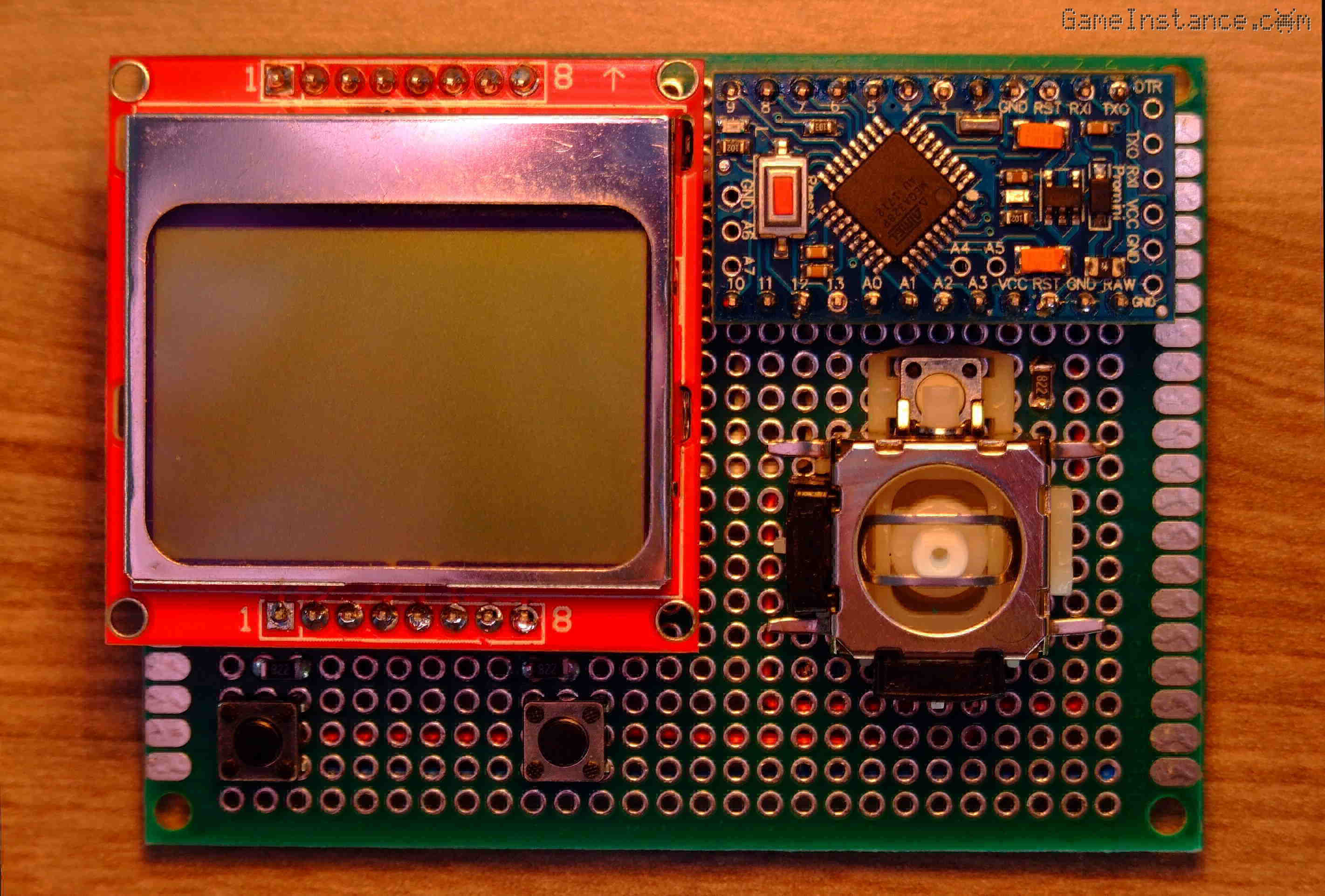 Game console - the initial revision
What better MCU for such an endeavor than the Atmega328. Heh, I could name twelve from the top of my head but the idea is to keep it simple. On the same note it'll be using the famous Nokia 5110 LCD. Any respectable game console needs a dual-axis joystick and at least two buttons. This one will have those as well. Sounds fun already? Keep reading.
With no further ado, here's what you need to build it:
BOM:
MCU1 - 1x Arduino Pro Mini (or a clone) featuring the Atmega328
LCD1 - 1x Nokia 5110 LCD module
JOY1 - 1x Dual axis analog joystick
SW1,2 - 2x Micro Switch Button
R1-3 - 3x 8.2 kOhm SMD resistors
Miscelaneous:
Female single-pin header connectors
PCB prototyping board 8cm x 6cm
Multi-color wires
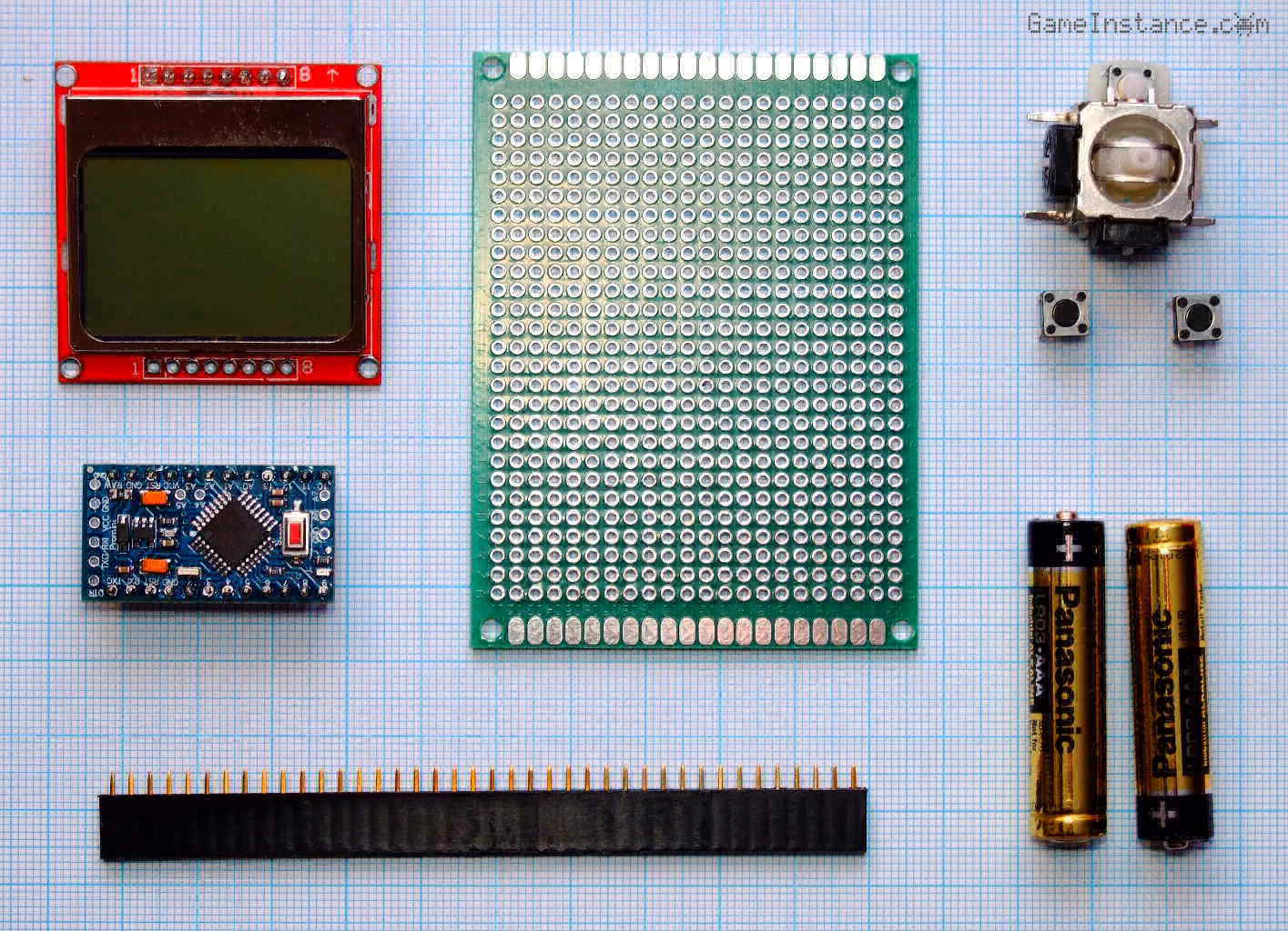 Game console - the spread bill of materials
The circuit
has its roots in the Snake Game configuration. Some LCD connection changes have been made to simplify the wiring process. Hooking up the analog joystick is even more straight-forward.
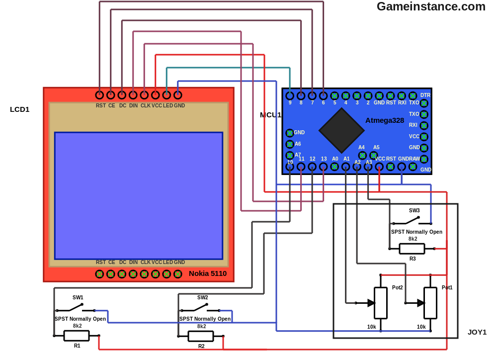 Game console schematics
Step-by-step build procedure
The component face - always start by soldering the smallest components first. It is easier than the other way around. Also, verify the switch poles before placing the micro-switches. You'll hate it if one turns out to be soldered permanently ON.
1. The R1 resistor - at [B5, C5]
2. The R2 resistor - at [J5, K5]
3. The R3 resistor - at [Y13, Y14]
4. The SW1 switch - at [[A2, A4], [C2, C4]]
5. The SW2 switch - at [[J2, J4], [L2, L4]]
6. The Joystick SW3 switch - at [[U12, U14], [W12, W14]]
7. The Joystick Pot1 potentiometer - at [J8, J9, J10]
8. The Joystick Pot2 potentiometer - at [E5, F5, G5]
9. A 12 pin header line for Arduino - at [A16-L16]
10. A 12 pin header line for Arduino - at [A22-L22]
11. An 8 pin header line for Nokia 5110 LCD - at [R22-Y22]
12. A 2 pin header line for the mechanical support of the LCD - at [R7, S7]
13. A 2 pin header line for the mechanical support of the LCD - at [X7, Y7]
 Game console - the component face
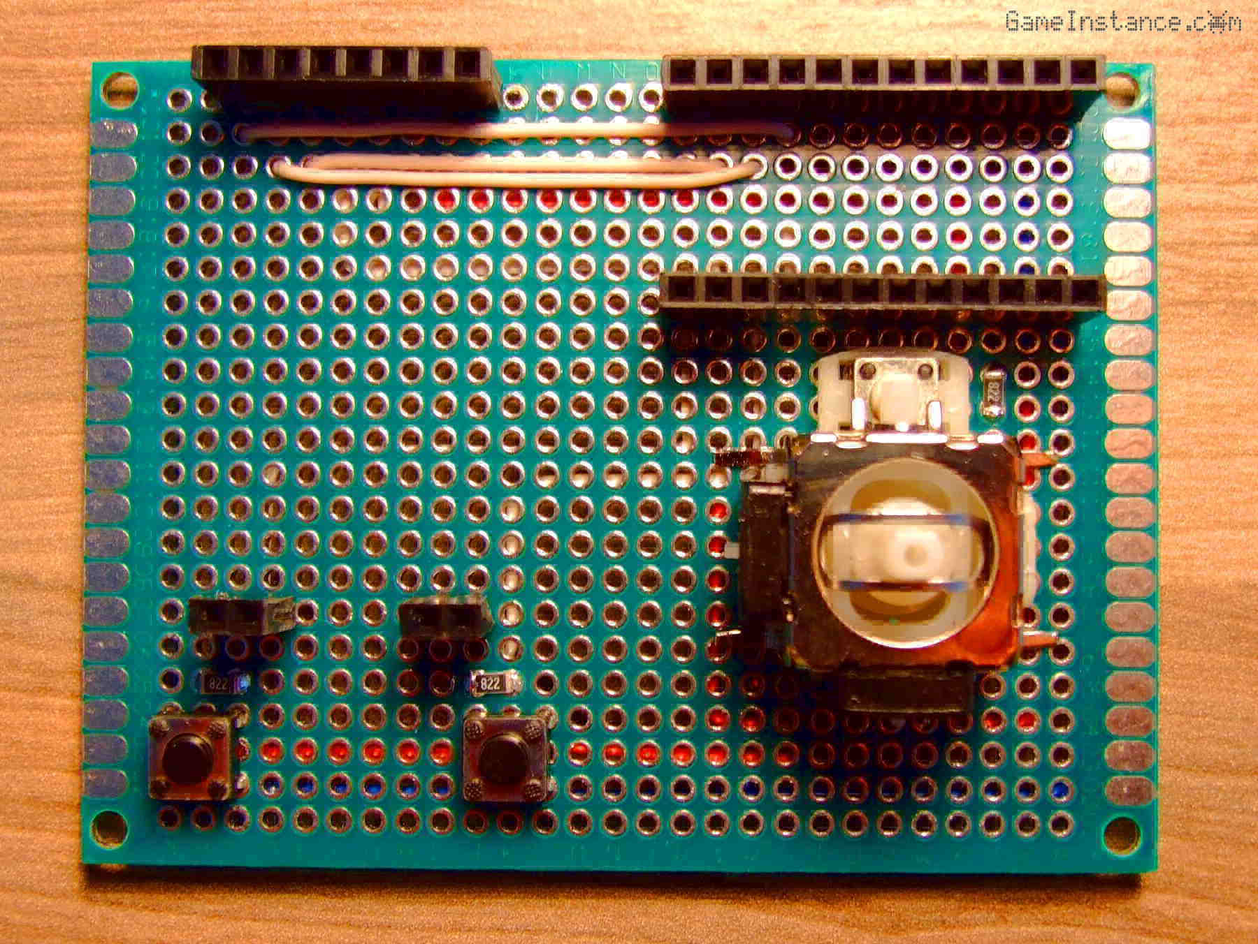
The wiring face - can be routed directly, from one point to the other. I prefer following the rows and columns wherever possible. If you do too, make sure you avoid places where parts or nodes need to be soldered later on :)
1. The GND lines - at
[B16, R22], [B16, A12], [A12, E12], [A12, J2], [J2, J5], [J5, J8], [J5, G5], [J2, P2], [P2, Y2]
2. The VCC lines - at
[D16, T22], [D16, C14], [C14, E4], [E4, E5], [E4, J10], [E4, Q3], [Q3, Q5], [Q3, Z5]
--- The LCD signal lines ---
3. The LCD LED light - at [L22, S22]
4. The LCD CLK - at [I16, U22]
5. The LCD DIN - at [K16, V22]
6. The LCD DC - at [K22, W22] - routed through the component face
7. The LCD CE - at [J22, X22] - routed through the component face
8. The LCD RST - at [I22, Y22] - routed through the component face
--- The Joystick signal lines ---
9. The SW3 C-button micro-switch - at [E16, E14], [E14, C13]
10. The Pot1 X-axis potentiometer - at [F16, F5]
11. The Pot2 Y-axis potentiometer - at [G16, J9]
--- The Buttons ---
12. The SW1 A-button micro-switch - at [L16, Y5], [Y5, Y4]
13. The SW2 B-button micro-switch - at [J16, R5], [R5, R4]
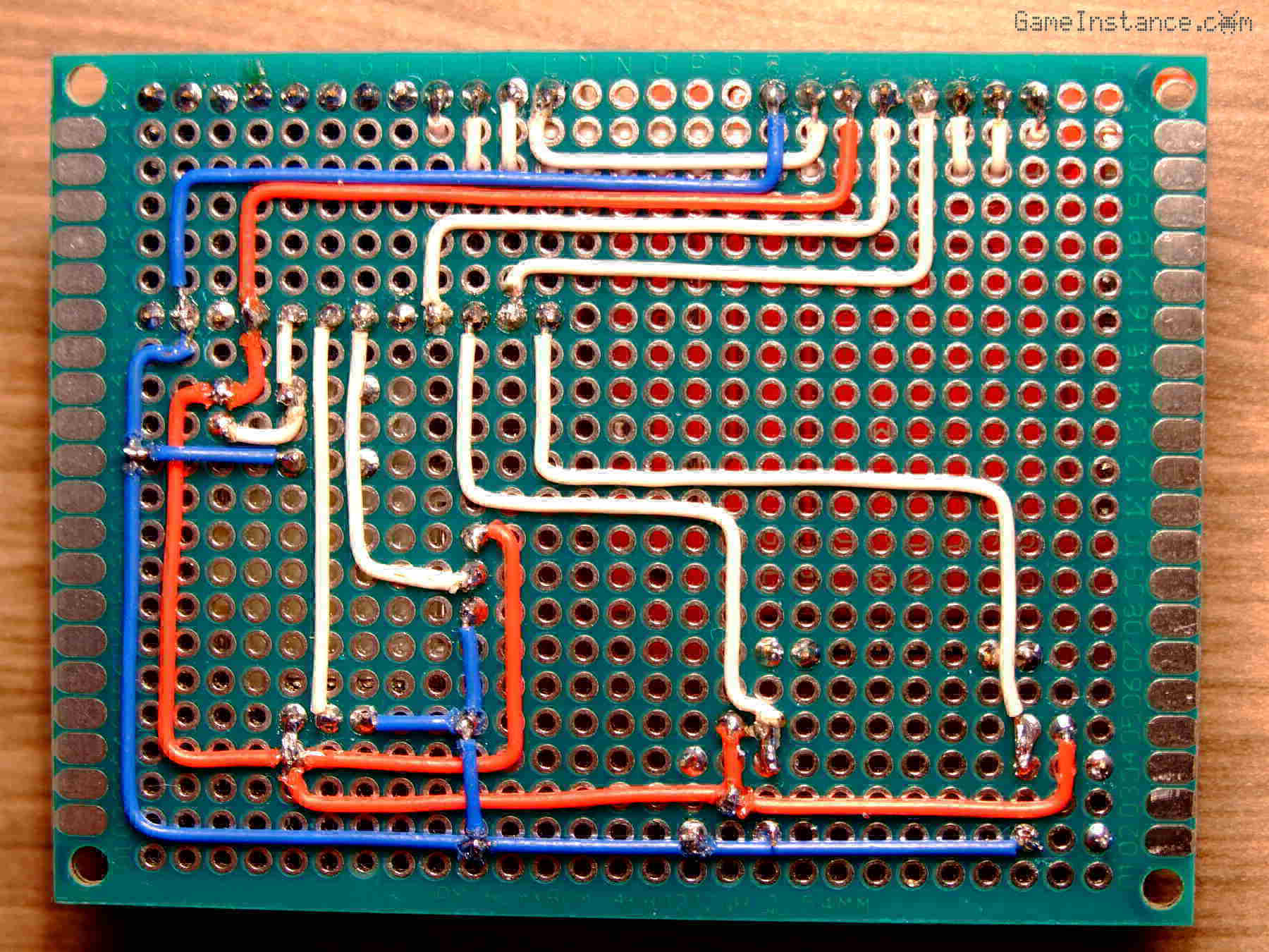 Game console - the wiring face
An aerie eye will observe 26 build steps. The superstitious will say that's bad luck, twice. The game corrupted mind will argue that bad luck and bad luck neutralize one another giving good luck. We can go on like that forever.
Now mount the Arduino and LCD modules into their corresponding locations and power the console. It won't work, obviously, because you need to flash the sketch beforehand.
The software
is open source and is an invitation to try your hand at building games. All you need is the game console, the Arduino IDE and a USB-to-serial adapter, such as the FTDI232 module. There's no GPU, no cache lines, not even multi-threading to handle. That leaves you with only simple tools to achieve it.
For the remainder of this section I will suggest using a class that interfaces the console hardware. It provides handy methods such as IsPressed and GetAxis or access the m_lcd display object. The GameConsole is abstract and needs to be implemented into your own class that overrides the Execute method. Here's an example:
#include <GameConsole.h>


/*
 *  Console calibration class.
 */
class Calibration : public GameConsole {

  public:
    /// default constructor
    Calibration() : GameConsole(),
      m_state(0),
      m_nowTime(0),
      m_lastTime(0) {
      //
    };
    /// destructor
    virtual ~Calibration() {
      //
    };
    /// the main method implementation
    void Execute() {
      //
      m_nowTime = millis();
      if (m_state == 0) {
        // initial game state
        m_lastTime = m_nowTime;
        m_state = 1;
      }

      if (m_state == 1) {
        // reading input
        ClearDisplay();
        if (IsPressed(BUTTON_A)) {
          //
          m_lcd.Text("A", 8, 32, true);
        }
        if (IsPressed(BUTTON_B)) {
          //
          m_lcd.Text("B", 68, 32, true);
        }
        if (IsPressed(BUTTON_C)) {
          //
          m_lcd.Text("C", 68, 8, true);
        }
        m_lcd.Text("X:", 24, 16, true);
        String s = String(GetAxis(AXIS_X));
        m_lcd.Text(s, 36, 16, true);
        m_lcd.Text("Y:", 24, 24, true);
        s = String(GetAxis(AXIS_Y));
        m_lcd.Text(s, 36, 24, true);
        m_lcd.Update();
        m_state = 2;
      }

      if (m_state == 2) {
        // waiting state
        if (m_nowTime > m_lastTime + 40) {
          //
          m_lastTime = m_nowTime;
          m_state = 1;
        }
      }
    }


  private:

    /// the state of the automate
    byte m_state;
    /// high-res time probes
    unsigned long m_nowTime, m_lastTime;
};

/// the game instance
Calibration game;

void setup() {
  // put your setup code here, to run once:
  game.Setup();
}

void loop() {
  // put your main code here, to run repeatedly:
  game.Loop();
}
The program displays the joystick position on the X, Y axes and shows the pressed buttons. Do observe the use of millis Arduino function in a waiting state instead of the old delay. Get used to it because from now on this will be the way to go for non-blocking waits.
Check out every now and then the Github repository for updates.
Few words of wisdom
The console works if powered by two AAA 1.5 volt alkaline batteries but the MCU will run at half the clock speed. Just hook them in series between the VCC and GND pins. Should you choose a DC power supply providing more than 5.5 volts, make sure you connect it to the Arduino's RAW pin instead of the VCC.
To avoid all sorts of unpleasantries, cover the wired back side of the board with a plastic sheet, wood board, what-have-you to prevent accidental sort-circuits. If you don't, at least avoid wearing metal rings or jewelry that might get into contact with them.