A perfectly functional A2DP Bluetooth module powered by the enigma chip C7THN50004. Although no search engine seems to know about it yet, it does what it promises: outputs two preamplified audio signals. Wiring it is straightforward but getting a noiseless output requires a little tinkering.
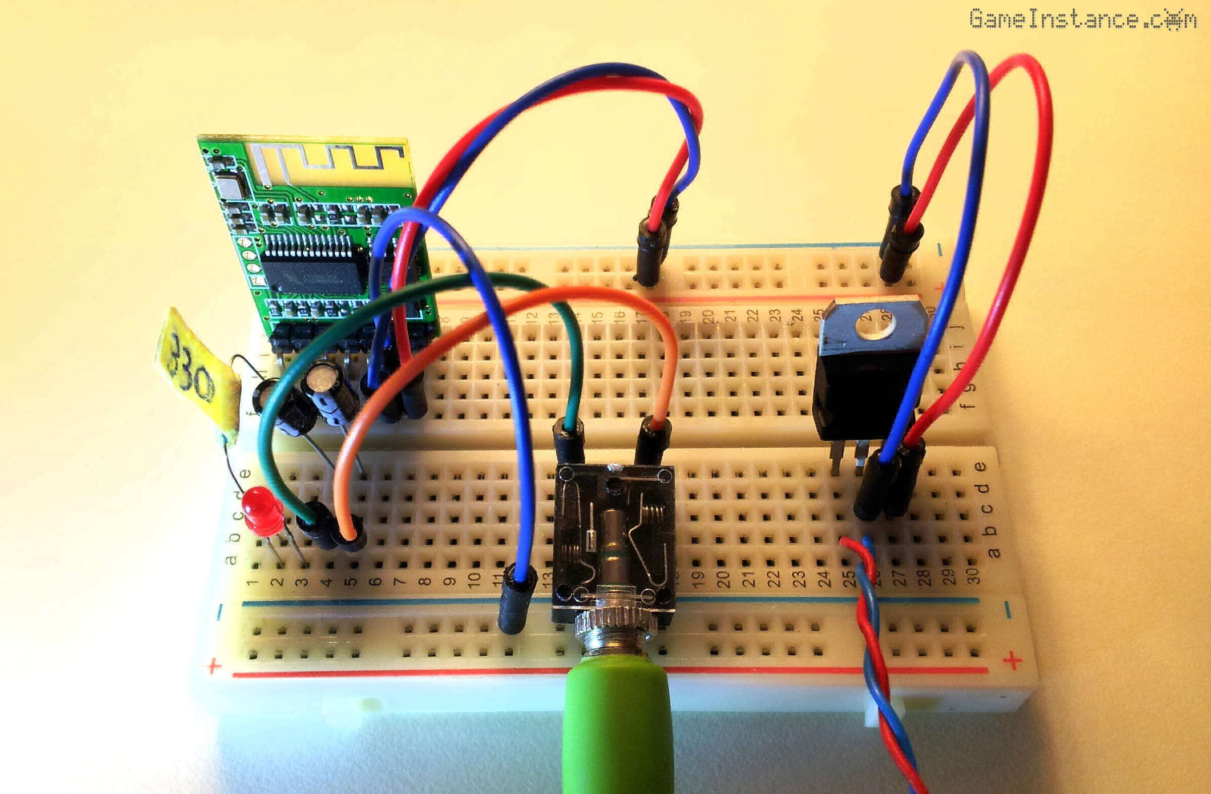
 A2DP Bluetooth audio module WIN-668 - breadboard circuit
But first
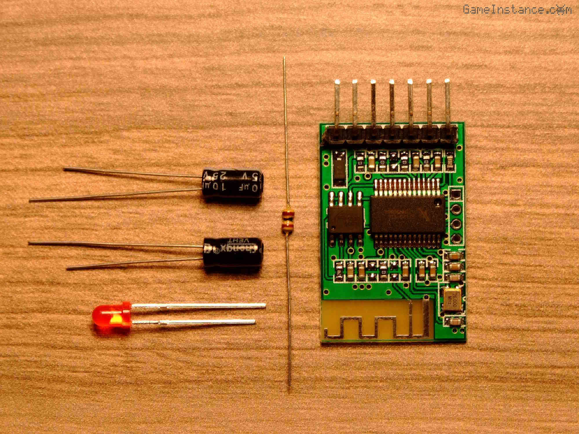
this is what you get for 1.6 dollars: the 3x2 cm board ending with a seven pin male header connector, one red LED, one 100 Ohm resistor and two 10uF electrolytic capacitors. You won't need anything else to get it working besides headphones and a 5V power source.
 A2DP Bluetooth audio module WIN-668 - package contents
The board
is dominated by the mysterious 28pin SOIC chip branded C7THN50004/17120-11P and the ZD25D80 which is an 8 Megabit Serial Flash memory. This is a prototyping board and as such it has a polarity protection diode on the 5V input and the breadboard friendly 2.54mm pitch male breakout connector. Right next to the main chip, the board presents a four pin connector - not soldered though - most likely for UART communication.
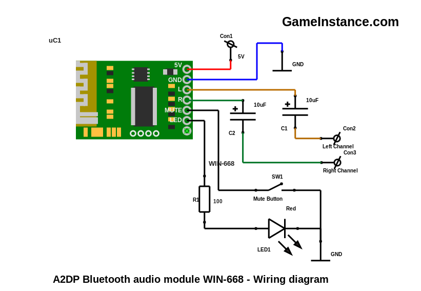
Most important for your application are six of the seven breakout pins: 5V and GND for powering the device, L and R audio outputs, MUTE input for the obvious purpose and one LED output. The seventh pin is not marked although it is connected to the first pin of the main chip.
An assumption
can very well be that the seventh pin is used for reseting the chip before flashing it via the four pin serial connector. Another theory is that the chip itself can do remote serial communication, much like the SPP-CA. For all I know it can even do AVRCP. None of those can be confirmed yet since there's no datasheet available.

Wiring the circuit takes few minutes. The SW1 is optional and can be ignored if you're not planning on muting the outputs. However, the LED is useful and since you have all the parts I advise you to cable it as well. It indicates the Bluetooth connection status. Fast blinking means that the device is not paired, full on LED means it has paired and slow blinking LED indicates that it's paired and receiving audio data.
Careful now!
Do not ignore the C1 and C2 coupling capacitors. They eliminate the DC component generated by the module which is around 1.4 volts per channel. Dropping that kind of voltage on a low impedance input - say your regular headphones - would draw too much current for the module. Constant heat will be generated both on the module side and in the speakers prematurely shortening their lives.
Conclusions
This module has its drawbacks. When used on a breadboard, it picks noise from the power cables that gets amplified and passed over the output signal. I found that making a loop in the power cables (5V and GND) and folding them to the back of the breadboard solves the problem. No doubt it would work better on a well designed PCB.
I won't give pros and cons for it because it is the only A2DP tested so far. If you're thinking of upgrading your DIY stereo system, this may be what you're looking for. It is small enough to fit in any existing amplifier/preamplifier box. It can even fit in a circumaural set of headphones, if you're thinking of a mobile solution. However, in that case consider using a higher power battery pack as this particular model is in the energivore class.