Having decided on the electric circuit layout of the LEDs, I'm now moving on to the box build. In a nutshell, it will be composed of two white melamine MDF boards containing the UV LEDs that will be enclosed with 5 mm plywood panels and covered by two 4 mm Plexiglas sheets. It will have a dedicated compartment for the high-voltage electric components and one for the Arduino along with the display, buttons and relay control circuit. The cables running from the bottom to the lid will also be protected by a wiring chamber.
Box sizes
The only restriction applying to this box is given by the size of the precut Plexiglas sheet, in my case 50x25 cm. That dictates the length of the exposure compartment to be 25 cm. The value for the width is 20 cm and has been chosen to obtain an even distribution of 100 LEDs over the entire surface of the white board.
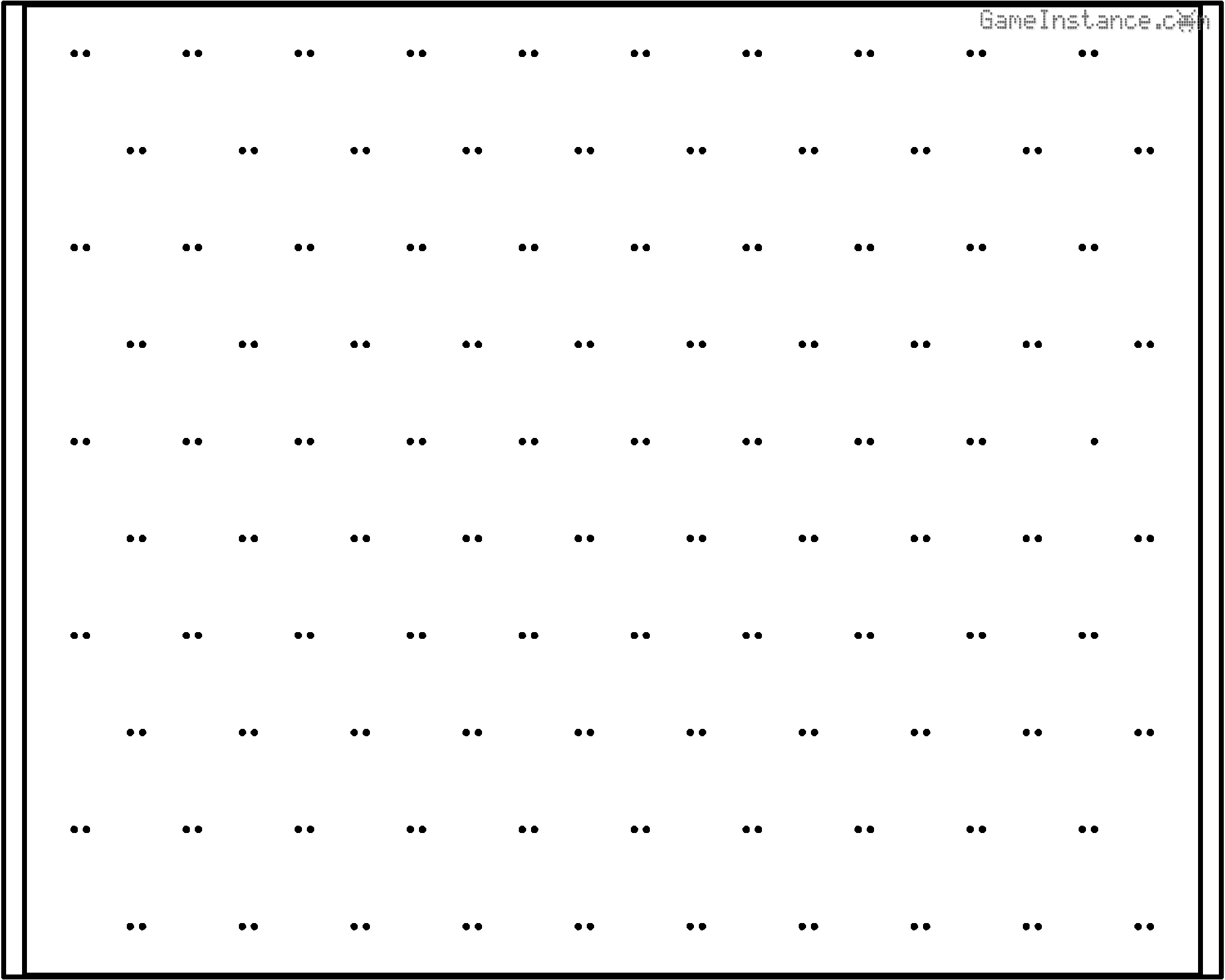 UV-Box - Drill chart for the exposure board hosting 100 triangularly distributed LEDs.
The height of the box will be determined based on the minimum distance between the LED and the exposure surface. The minimum distance is obtained considering the layout and the distance between the LEDs as well as the angle of light projection. I chose to distribute the LEDs in a triangular shape rather than square to get a better light coverage at the minimum distance. So, for a distance of 2.3 cm between the LEDs, the minimum height at which the beams merge to a homogeneous light projection on the exposure surface is 4 cm.
Considering the dimensions for the compartments and the wall thickness, the box will measure 32 x 21 x 12 cm at the exterior.
BOX DIMENSIONS: [mm]
Lid top board: (rectangle) x1 [ 276, 208 ]
Lid side board: (right trapezoid) x2 [ [ 309, 271 ], 49.8 ]
Lid panel board: (rectangle) x1 [ 208, 69.65658619254894 ]
Lid back board: (rectangle) x1 [ 208, 49.8 ]
Lid cable inner board: (rectangle) x1 [ 198, 49.8 ]
Lid MCU inner board: (rectangle) x1 [ 198, 44.8 ]
Lid MCU cover board: (rectangle) x1 [ 198, 43 ]
Box bottom board: (rectangle) x1 [ 319, 208 ]
Box side board: (rectangle) x2 [ 309, 59.099999999999994 ]
Box front/back board: (rectangle) x2 [ 208, 59.099999999999994 ]
Box cable inner board: (rectangle) x1 [ 198, 59.099999999999994 ]
Box MCU inner board: (rectangle) x1 [ 198, 54.099999999999994 ]
Box MCU cover board: (rectangle) x1 [ 198, 43 ]
Preparations
I've cut the boards by hand, which is a painstaking process. If you do the same, be ready for the bad part: the cuts won't be straight and you'll have to file-down each side of each piece. Of course, you'll have to take into account this fact and allow at least 1 mm of extra tolerance on each side. Anyway, if you're fortunate enough and have a neighbor with a CNC machine or a table saw, just buy the man or the woman a couple of beers or a nice bottle of wine and ask him/her to do it. You'll thank me later!
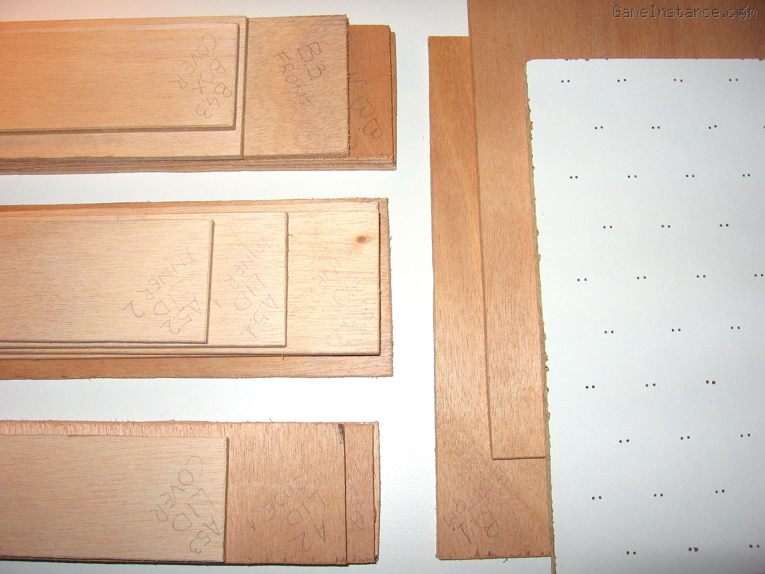 UV-Box - the not-so-straight hand-cut plywood panels
The 5mm plywood boards are not very rigid but given the small dimensions of the boards, that won't pose problems. Once you've put the pieces together the result is very sturdy. However, the 5 mm thick edge is not enough the glue the parts. That's why I got myself a 9x9 mm pine-wood bar of approximately 2 meter long from which I cut short sections to help gluing the boards together.
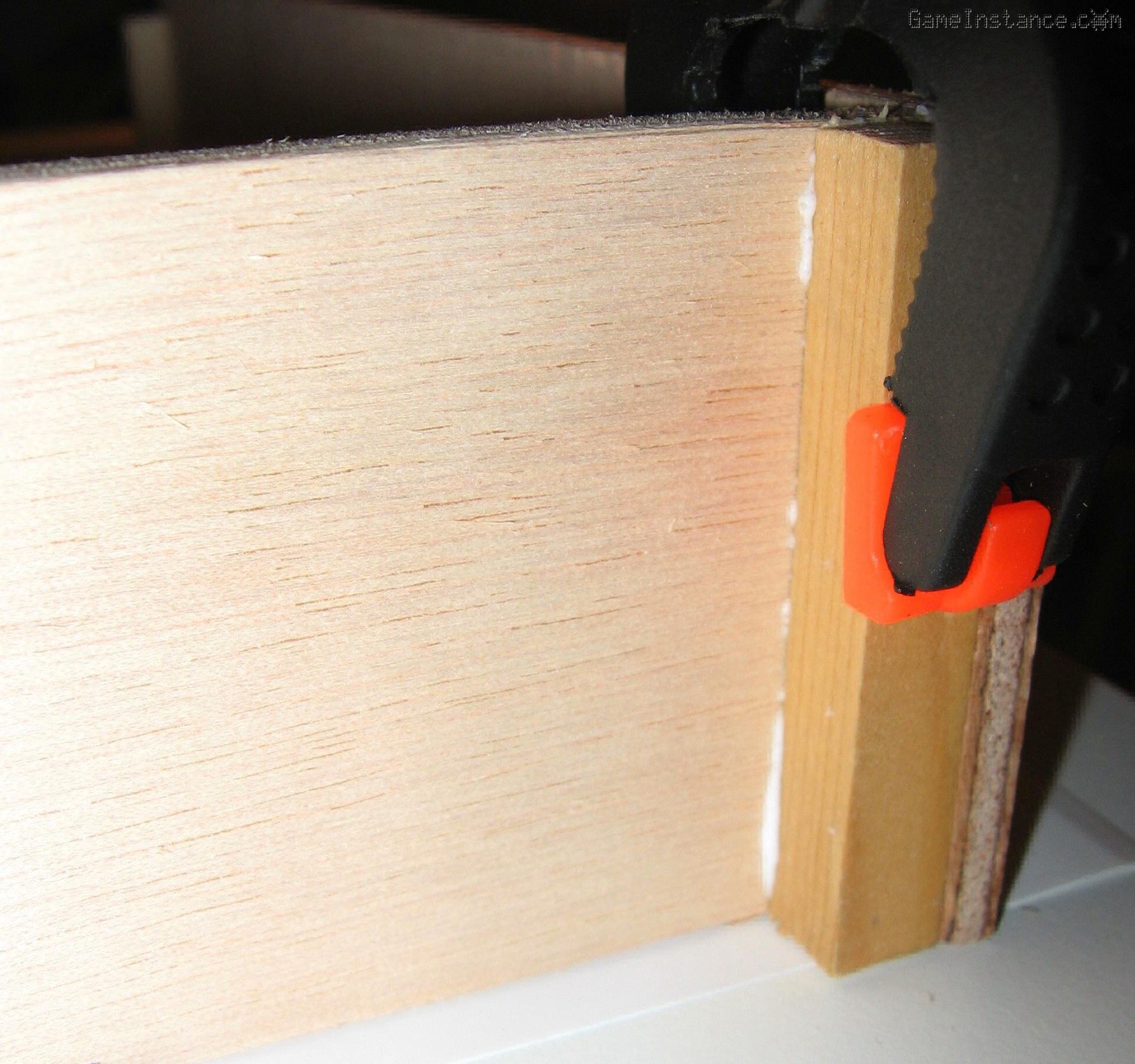 UV-Box - 9x9 mm wooden sections reinforcing the perpendicular joints between plywood panels
I've started building the bottom side of the box by mounting the side-walls onto the internal walls of the exposure chamber. Carefully measuring, marking, applying glue, placing the 9x9 mm sections on the 5 mm panels and then adjusting their position one more time before clamping the parts together. This is another long process as the glue needs time to cure.
Before you glue the bottom panel, drill a couple of holes on the lower side of the cable and electronics compartments panels. They should not be overlapping with the LED board nor go above it because they'll be used for running cables from one compartment to the next. Also, make sure you don't place 9x9 mm sections inside the exposure compartment.
 UV-Box - Bottom side almost complete. Observe the small holes on the lower edge of the compartment delimiting boards.
The lid
involves pretty much the same process except that it has an angled front-end that needs some extra preparation. The side panels of the lid must be cut as right trapezoids and the front panel has to be rasped-out. The 9x9 mm sections need to be angled as well.
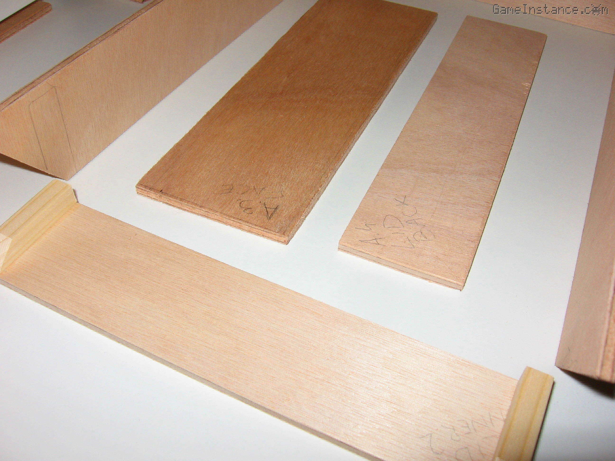 UV-Box - Angled cut lid side panels.
The angled front compartment will be housing the Atmega MCU, the 16x2 LCD, four buttons and a hall effect sensor. The later will be used for detecting lid opening to emergency stop the exposure.
 UV-Box - Cutting out the LCD slot on the front panel.
For the display, I started by drilling two large diameter holes in the opposite corners of the rectangle to be removed and continued from there with a jigsaw and a rasp. For the four buttons I drilled four 5 mm holes on the right side of the LCD - you may drill them on the left side if your left-handed. For buttons I used 5 mm LEDs, each of different color. They're long enough to reach the other side of the board and have a larger rim at the base preventing them from falling out.
The LED boards
are similar. They both host 100 LEDs on one and a half circuits. That won't be visible from the front but on the flip-side they'll will be slightly different: one board will have an extra current limiting resistor for one half of the circuit.
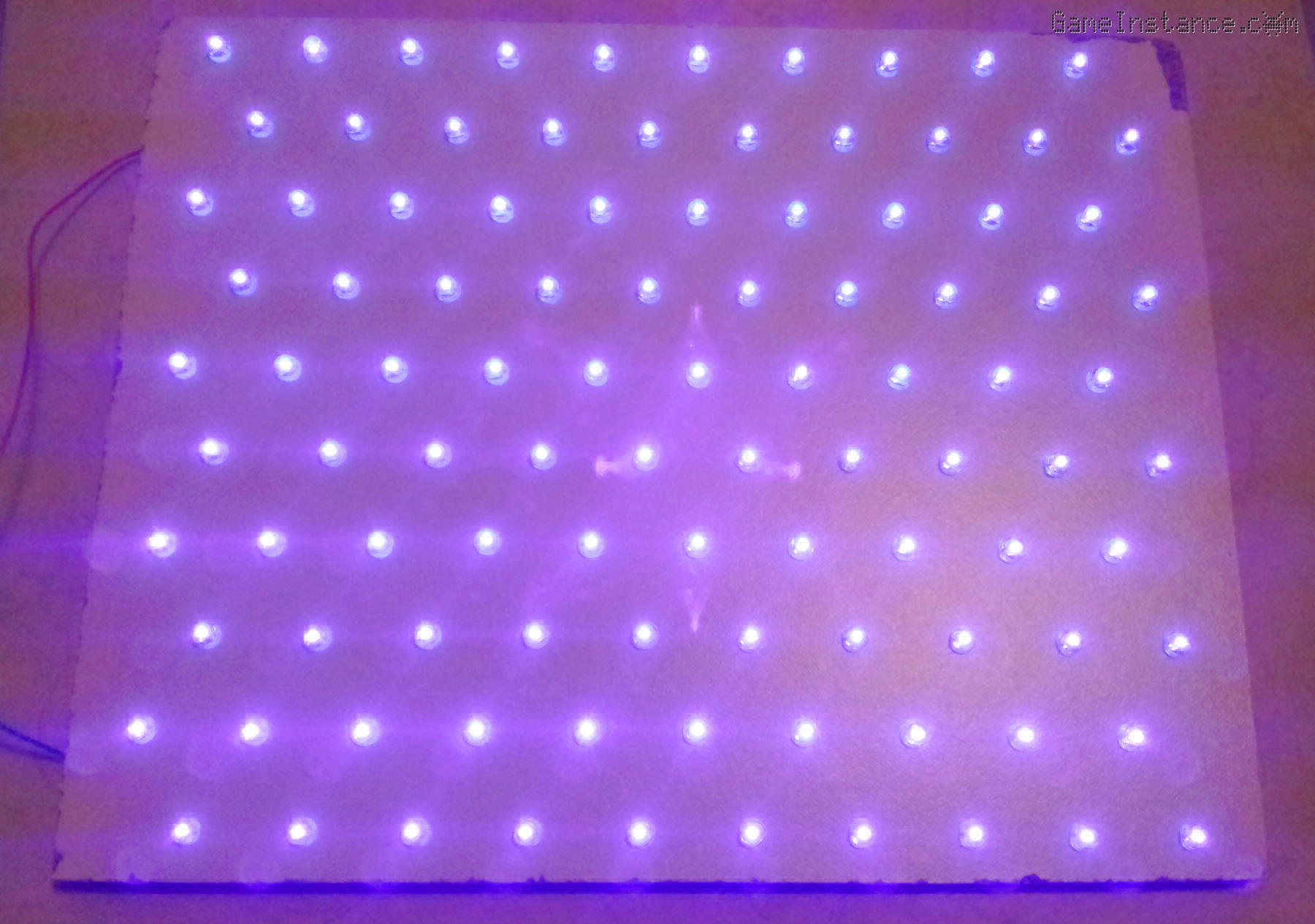
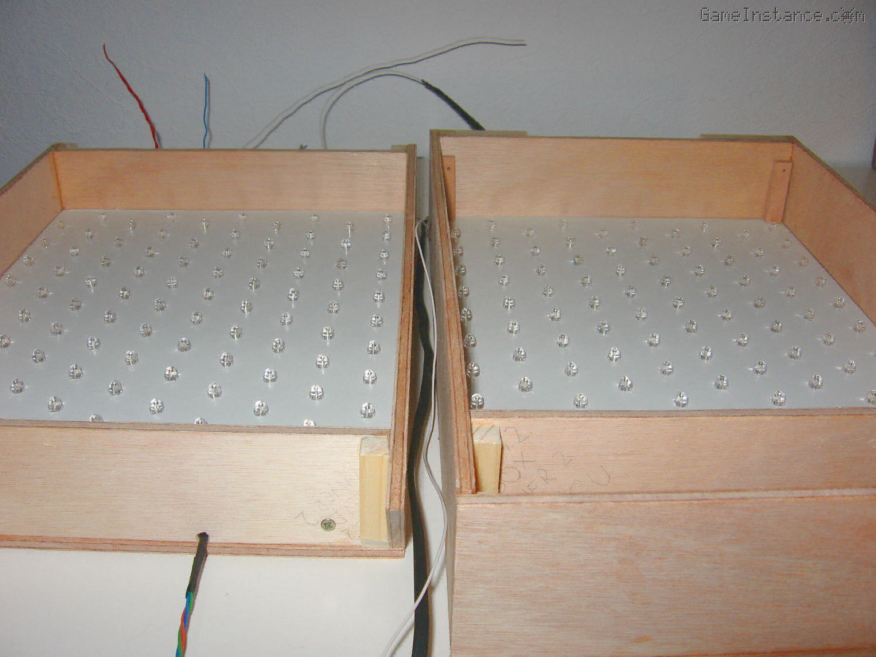
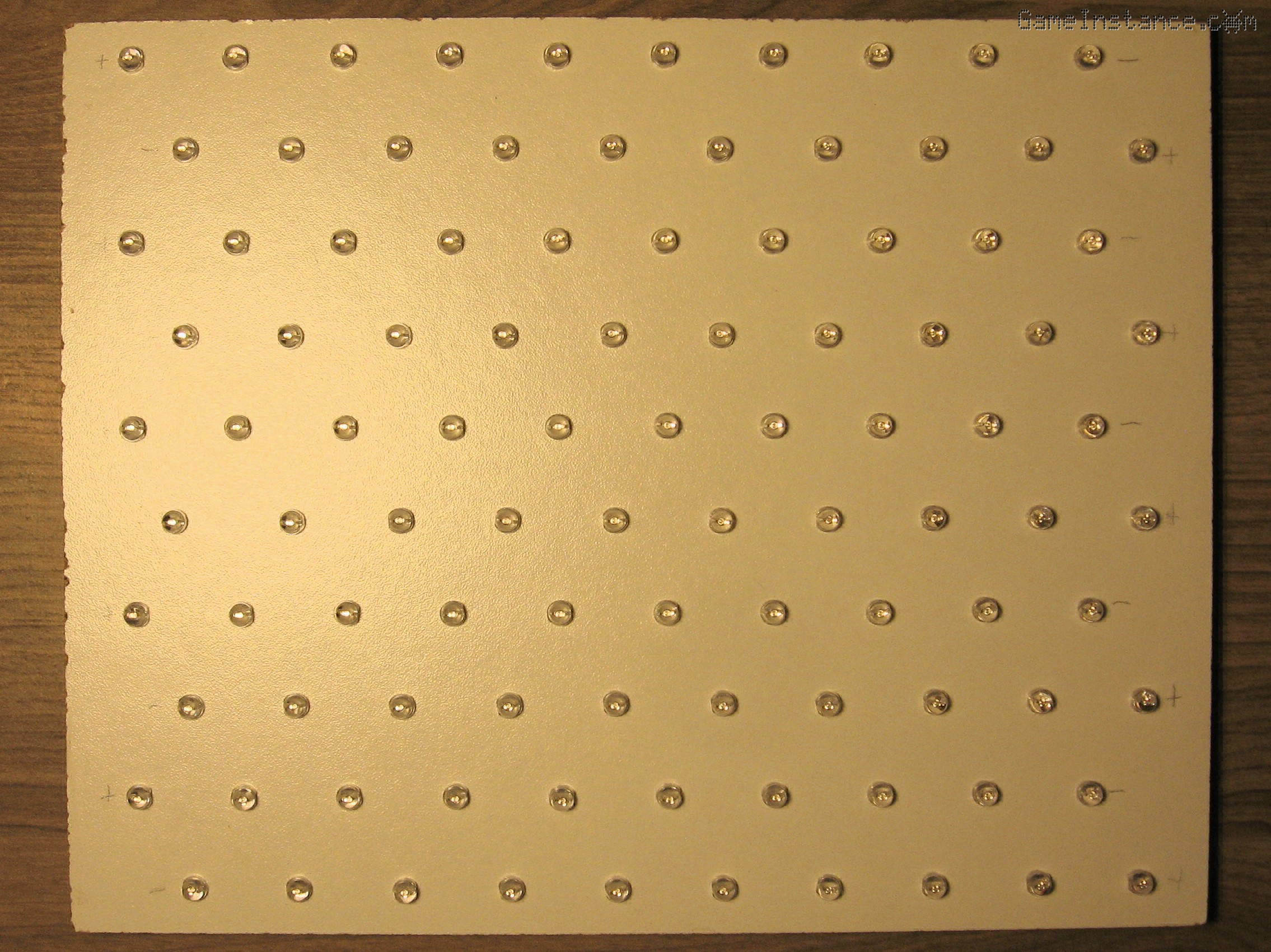 UV-Box - 100 UV LEDs placed in a triangular pattern on one of the exposure boards.
Warning:
UV radiation is harmful for your eyes. Do not look directly into the light produced by the UV LEDs. Use protective sunglasses and even so avoid long exposure.
As the glue was drying out I started placing LEDs and to my surprise I noticed that the UV LEDs I received had slightly shorter pins than the regular LEDs I tested with initially. That combined with the fact that my white LED board has 8 mm means that the pins of the neighboring LEDs won't get into contact when bent. Bummer!
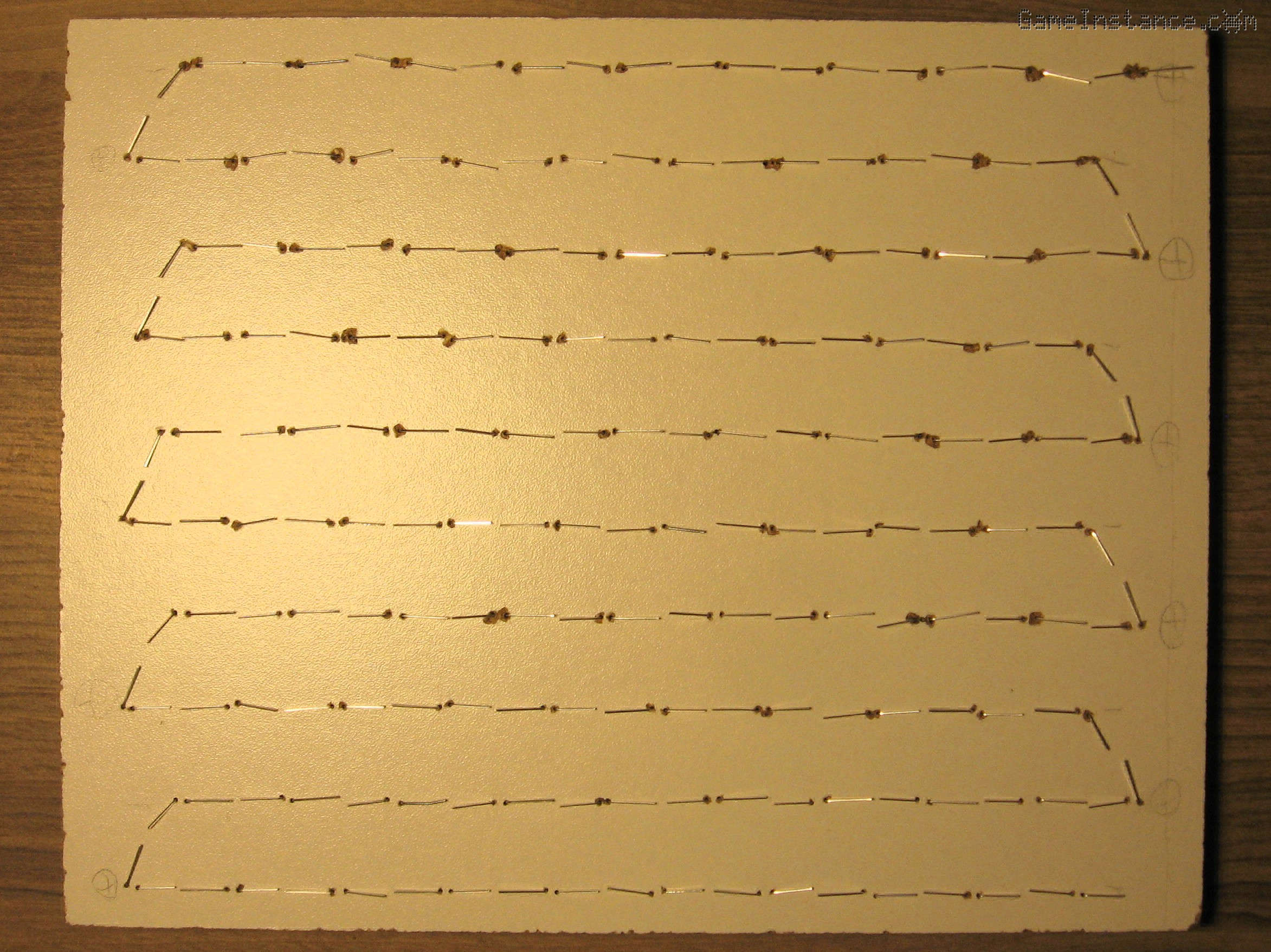 UV-Box - The back of the exposure board. LEDs not reaching each-other.
A thiner board would have altered the distance between the LEDs and the exposure surface. Not by much but I wasn't willing to give up on the already drilled boards either. I had no choice but to continue using the thick boards and after some head scratching I came up with a quick solution for joining the LED pins. I used a thick wire - thicker that the LED pins - as sample and lots of thiner wire to make joining sections. Each joining section was made in few seconds by winding thiner wire onto the thicker one, cutting it, removing it and then placing it in-between the LED pins. Very, very annoying at first but totally okay by the 200th.
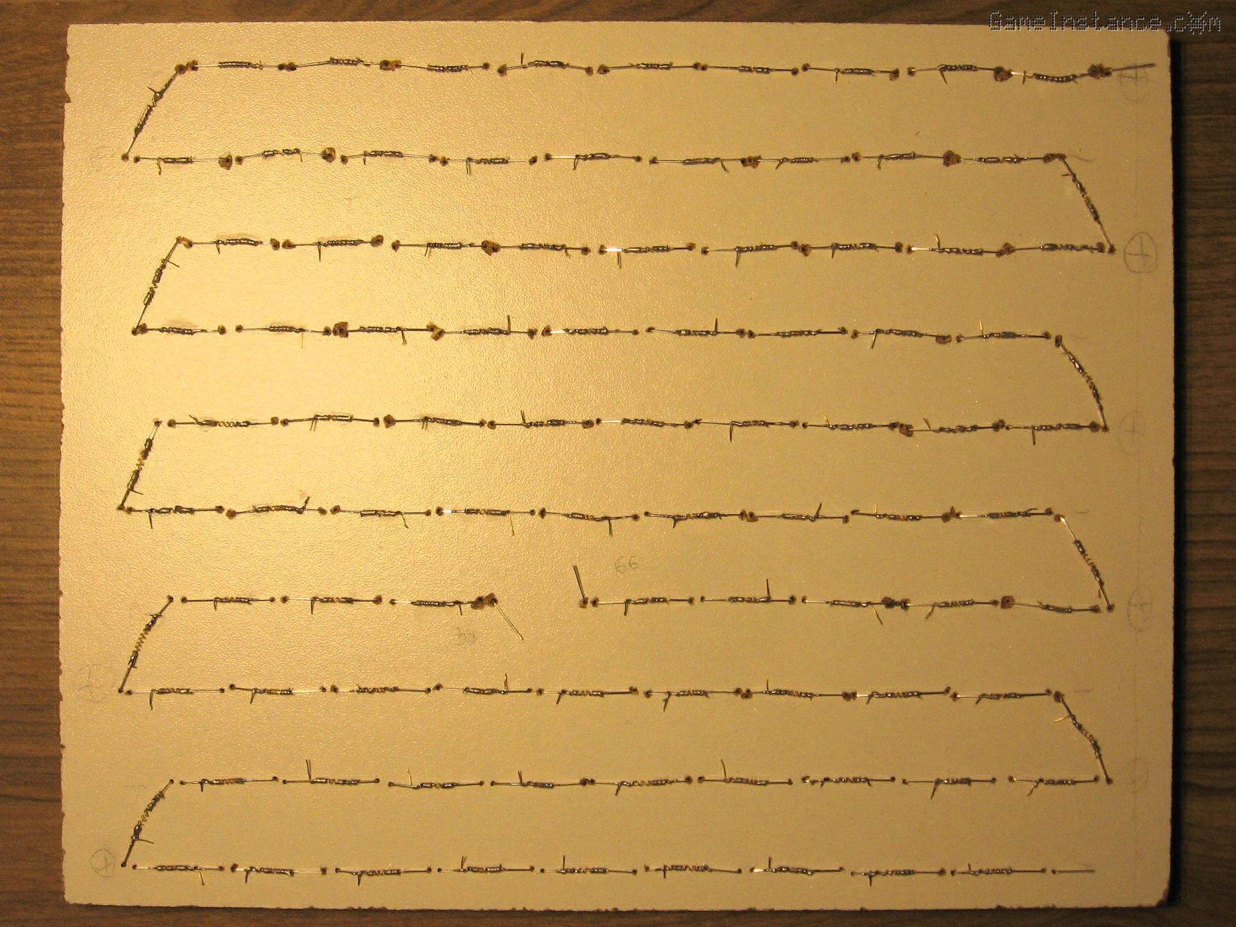 UV-Box - The hacky solution of joining the LED pins together using wound wire sections.
After soldering the current limiting resistors and the connecting wires I ran a test on each board. The LEDs seem bright enough. I looked at them through my camera's LCD and using sun glasses.
The wiring
was straightforward. I've run the AC wires from the back cable compartment all the way to the front through the previously made holes. I connected them to the rectifier board and then passed the DC wires back to the cable compartment.
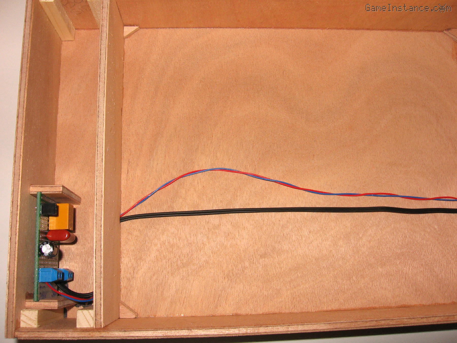 UV-Box - Wiring the bottom side. The high voltage electronics PCB can be observed on the left side compartment.
Warning:
This project involves HIGH VOLTAGE! Touching a high voltage live wire is DEADLY! Please take proper precautions if you are attempting to reproduce it.
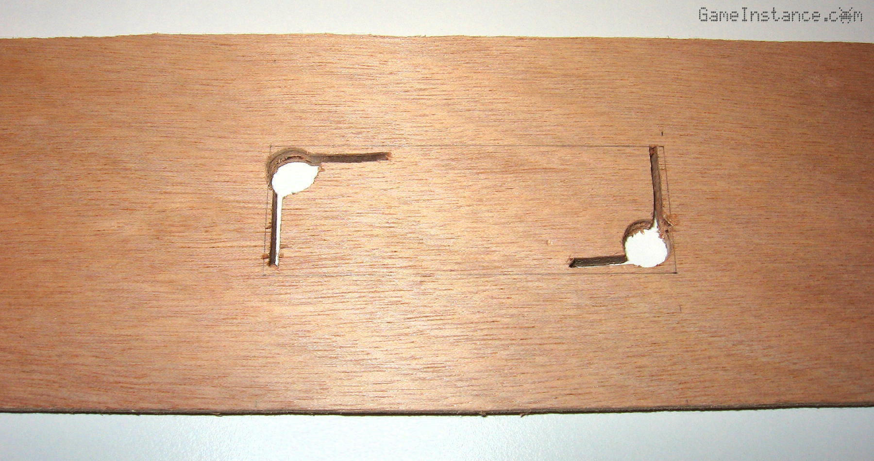
For the hopefully rare situations when the box lid needs to be removed I decided to use two screw connectors with three pins. They are glued on the inner wall of the cable compartment and should facilitate the solder-less removal of the top side. The connectors had to be trimmed to fit the 9mm available space.
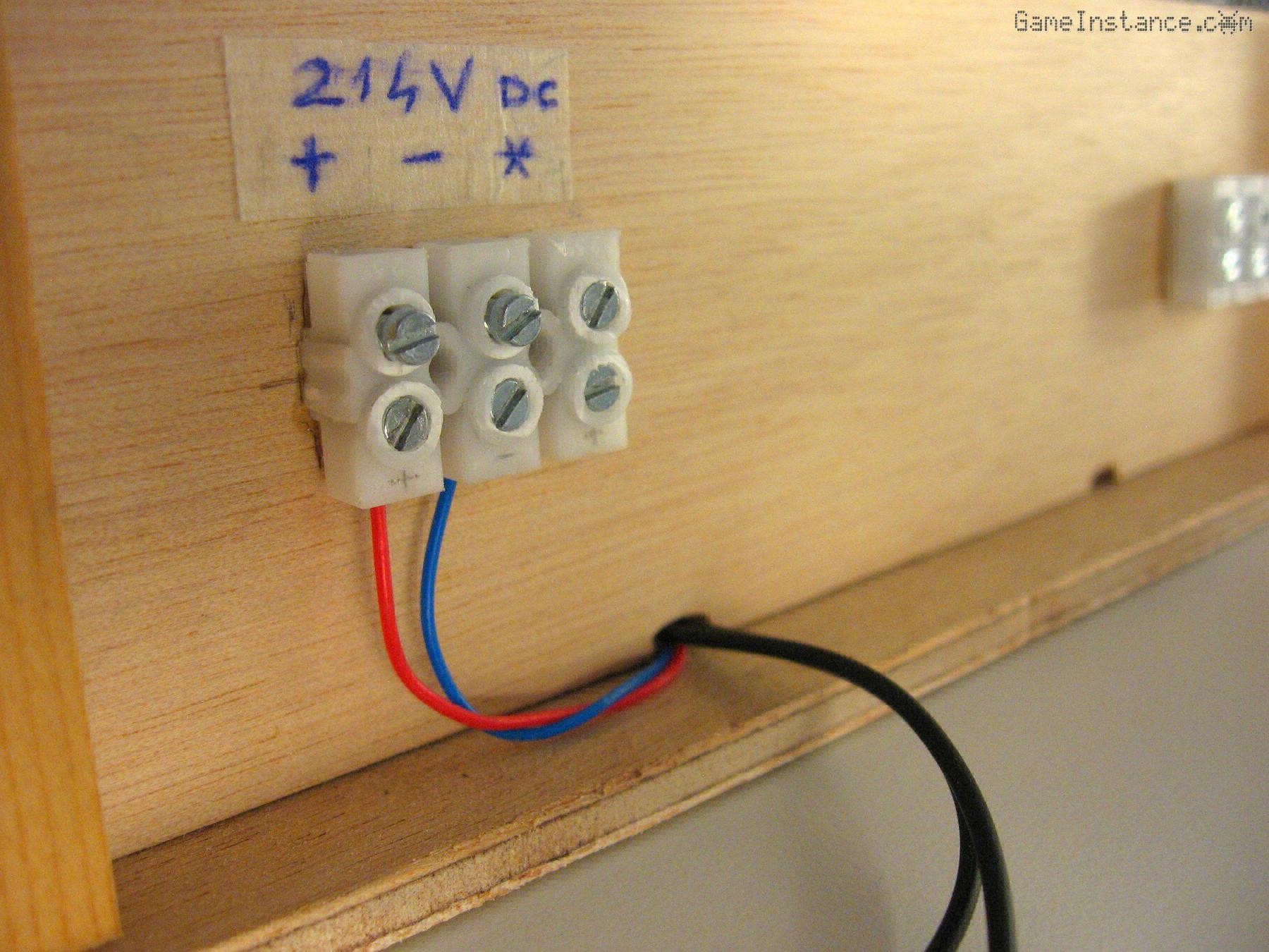 UV-Box - The two trimmed connectors in the lower half of the cable compartment.
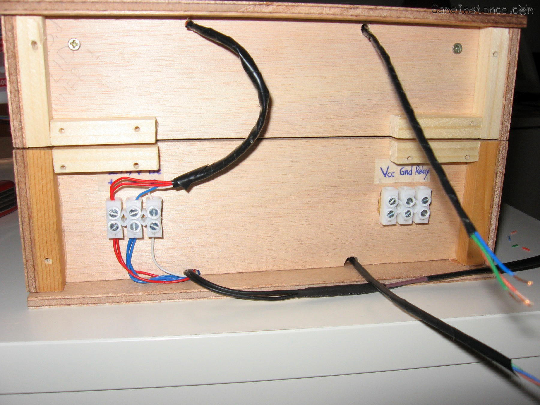
In case you're baffled by the star sign next to the plus and minus, that's the junction point between the top and bottom halves of the third LED series. The other connector hooks the top wires coming from the Arduino with the bottom section that leads to the 12V power supply. The two circuits are separated by a safe distance and should never get in contact.
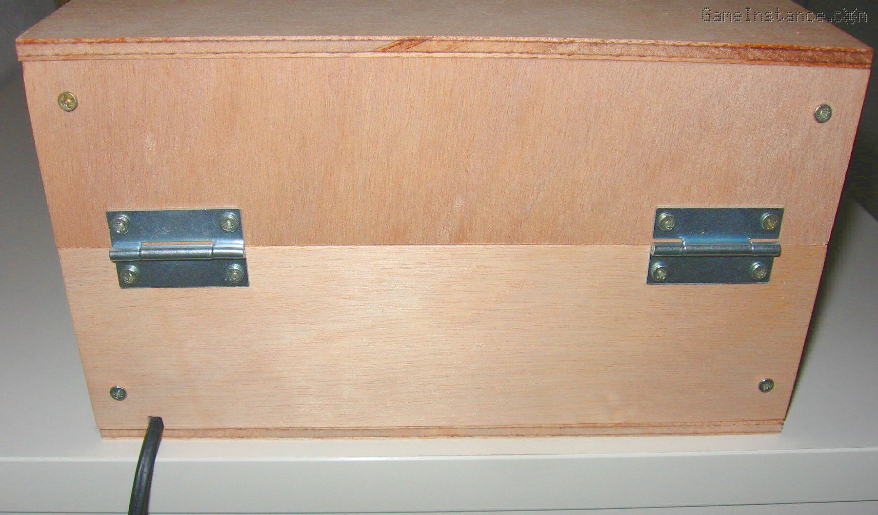
 UV-Box - The two halves of the box on top of each other.
To further protect the user from the high voltage circuit, the connectors in the cable compartment are covered with 9x9 mm sections. They also give rigidity to the box and help screwing in the back panels and the hinges.
The two LED boards have been lowered in and are resting on four 5 mm distancers on the bottom of each compartment. Four screws are keeping each board into position. Each screw is pushing from the cable/electronics compartment and are not visible. This solution is a bit more subtle. I prefer it rather then screwing the LED board onto the distancers.
The bottom LED board has another set of four distancers on top. The Plexiglas sheets are to be placed on them. I got the idea of gluing the two Plexiglas sheets together using pieces of ribbon. They're short enough to act as hinges but long enough to offer flexibility while in use. Because the sheets have the same size and drop perfectly in a narrow space, another ribbon will be glued on the top sheet. This will help you lift the top Plexiglas easily and handle the exposed PCB.
Milestone 3
After connecting the wires and hinging together the bottom part with the lid, I did a quick test to see that the relay works and all the LEDs light up. So far so good. I'm left with Arduino sub-project and its compartment. I foresee that's going to be a crazy experience given the tight space and the weird angles.
That is another story to be told in a next episode of "UV-Box 400". Yeah, I probably should name it.
Update: Part 4 - The Arduino MCU compartment.