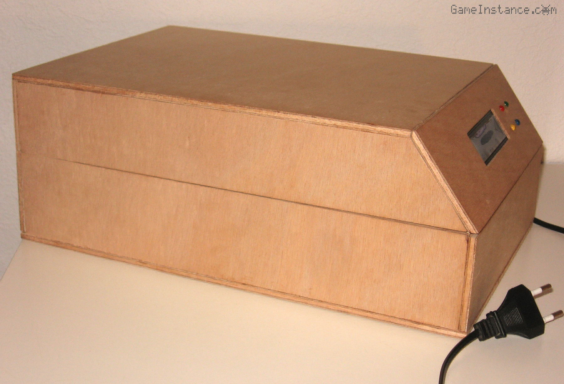
Little did I knew what I was getting into when I first decided on the angled facade. The box looks better this way, less boxy, but building it by hand wasn't quite the breeze I was hoping it will be. Anyway, I'll spare you the details and brief it all up. This article suggests an approach to squeezing a tiny MCU board next to the 16x2 LCD, mounting with the buttons, the hall effect sensor and finally, wiring them up. Enjoy!
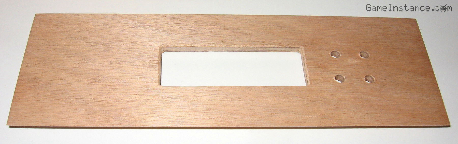
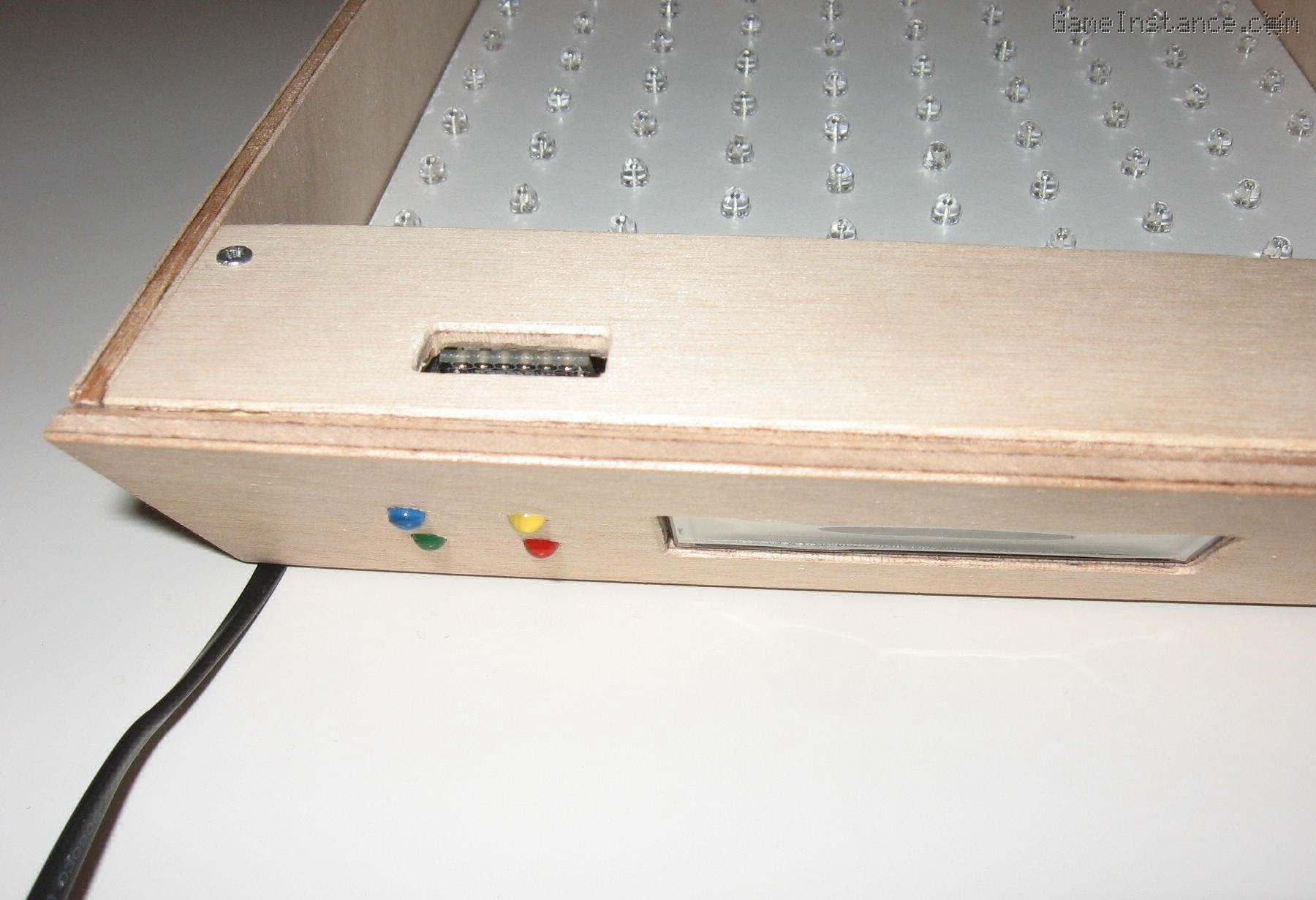
The front panel
was cut, filed and drilled to host the 16x2 LCD and the four buttons. There was no wiggle space as to what goes where in this aspect because the MCU board size, location and layout imposed some rigorous restrictions. This is how it turned out.
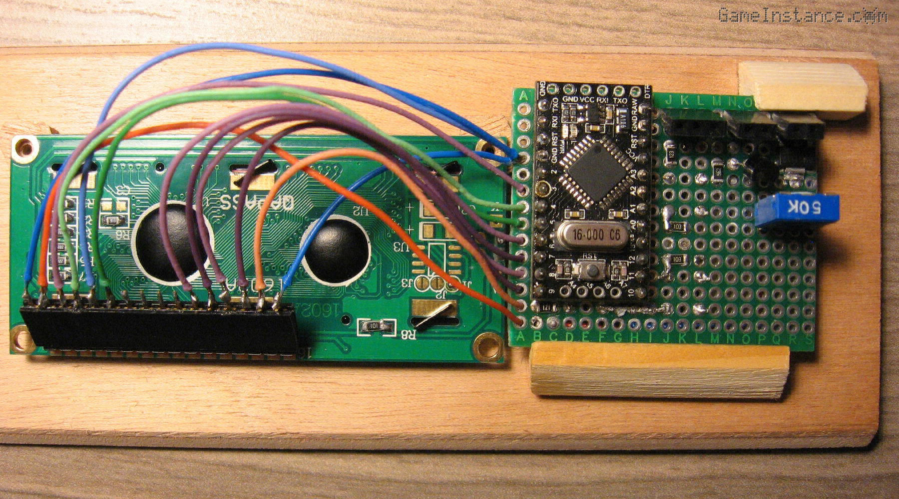
The smallest prototyping board I had, a 6x4 cm, wouldn't fit anywhere in the triangular prism. Not intact. I was thus forced to trim more than 1 cm out of it and even so the Arduino Pro Mini board was sticking too high above to the main board to be contained in that space. Few hours and dozens of curses later it came to me that I can carve-out a slot in the MCU compartment cover and leave the Pro Mini stick out. All I had to do was to create a layout that would allow the Pro Mini stick out the FTDI 232 header so that I can somehow benefit from this botched execution.
The PCB mounts
I had to cut so much out of the prototyping board that it no longer had no fixation holes. I chose to trade them over the usable surface for the components. As such, I had to manufacture some wooden slots in which the board would slide. Its definitive fixation was to be made by the screwed-in LCD. This is far from elegant but it works given the circumstances. Once again, DIY at it best ...
To avoid a short-circuit due to their proximity, the LCD and the PCB were later separated by plastic buffers. Also, the female header solder points were covered with molten plastic. This further strengthens the LCD connector and prevents accidental contacts when handling the electronics in such confined spaces.
The PCB layout
is by far the worst I made so far and hopefully it will be my last. I could have opted for an UV exposed and then etched PCB because the UV LED part of the box already functioned. If you're thinking of the classic chicken and egg dilemma, no, it did not apply here because I had a headless chicken able to lay eggs, so to speak. I haven't yet experimented the other steps of PCB manufacturing - a new project in itself - and that put me off the idea. So, I stuck with what I knew it will work: hand-wired prototyping boards. I won't post any pictures of that. It is that horrid.
Cherry on top, I ran out of low melting point solder when I soldered the little thingies that interconnect the UV LEDs so I had to use high melting point solder. That made the contact points look bad and melted the wire insulations. Quite a spectacle!
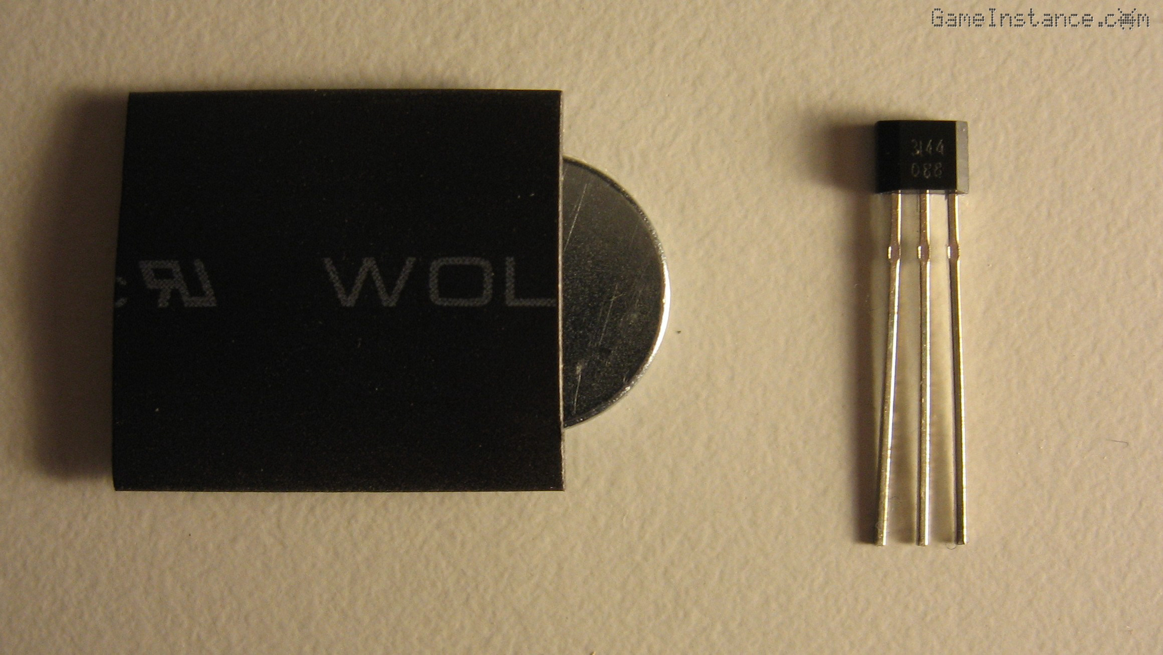
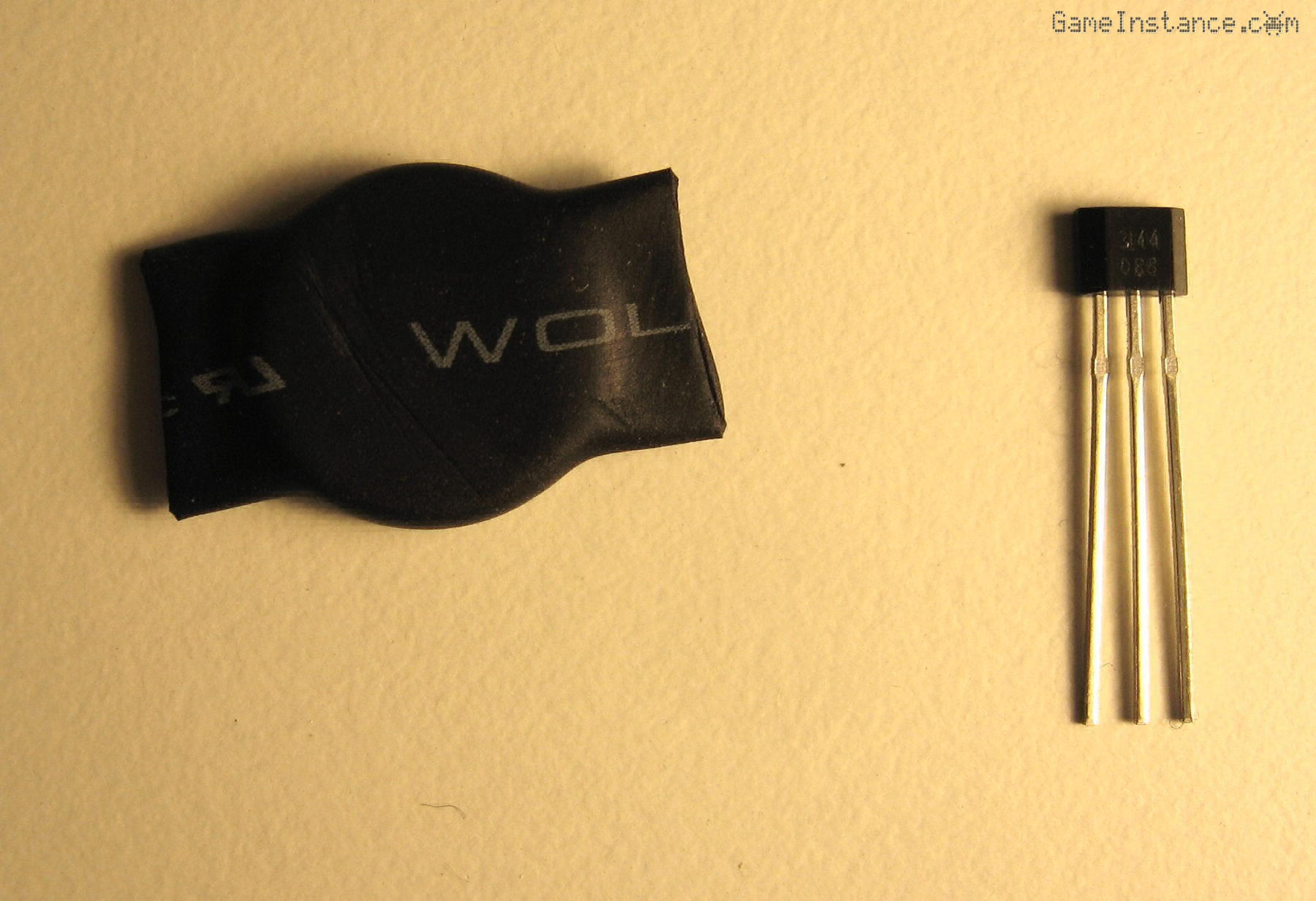
The Hall effect sensor
has the purpose of detecting the lid opening. I had to glue the sensor on the MCU cover and the neodymium magnet inside the electrics compartment, in the lower part of the box. Given the conductive nature of the magnet, I had to wrap it in a thermal shrink insulation sleeve.
I've cut the excess sleeve, soldered the sensor and gave it a try. Because it uses hysteresis to avoid oscillations, the distance at which it tunred on was rather small. Thus, the MCU cover would have to be placed flushed against the electrics compartment cover - which may never happen since my box was hand-made, thus imperfect. I wasn't happy with it and that meant more woodwork for me...
To bring the sensor closer to the magnet I carved slots for them in their corresponding covers. I kinda lost my patience there but I managed to solve it quickly.
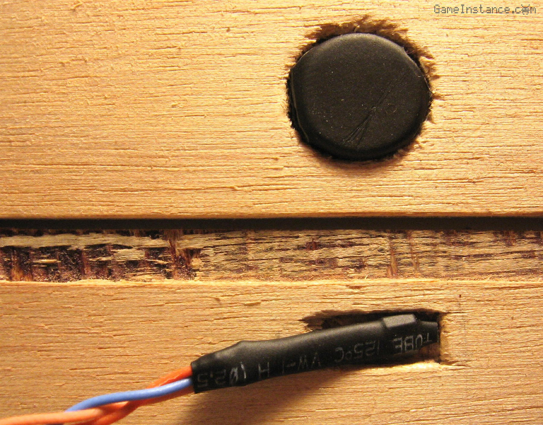
I've permanently glued the sensor and the magnet in their slots. The sensor has a three pin header connector that goes to the PCB and the magnet has nothing against that. Should I ever need to debug anything in there - hopefully never - everything is screwed in place. Removing them would be an easy job.
The MCU compartment
was also completely screwed in place, although only two screws are visible from the outside. It turned out reasonably well and the FTDI232 port doesn't look that bad after all.
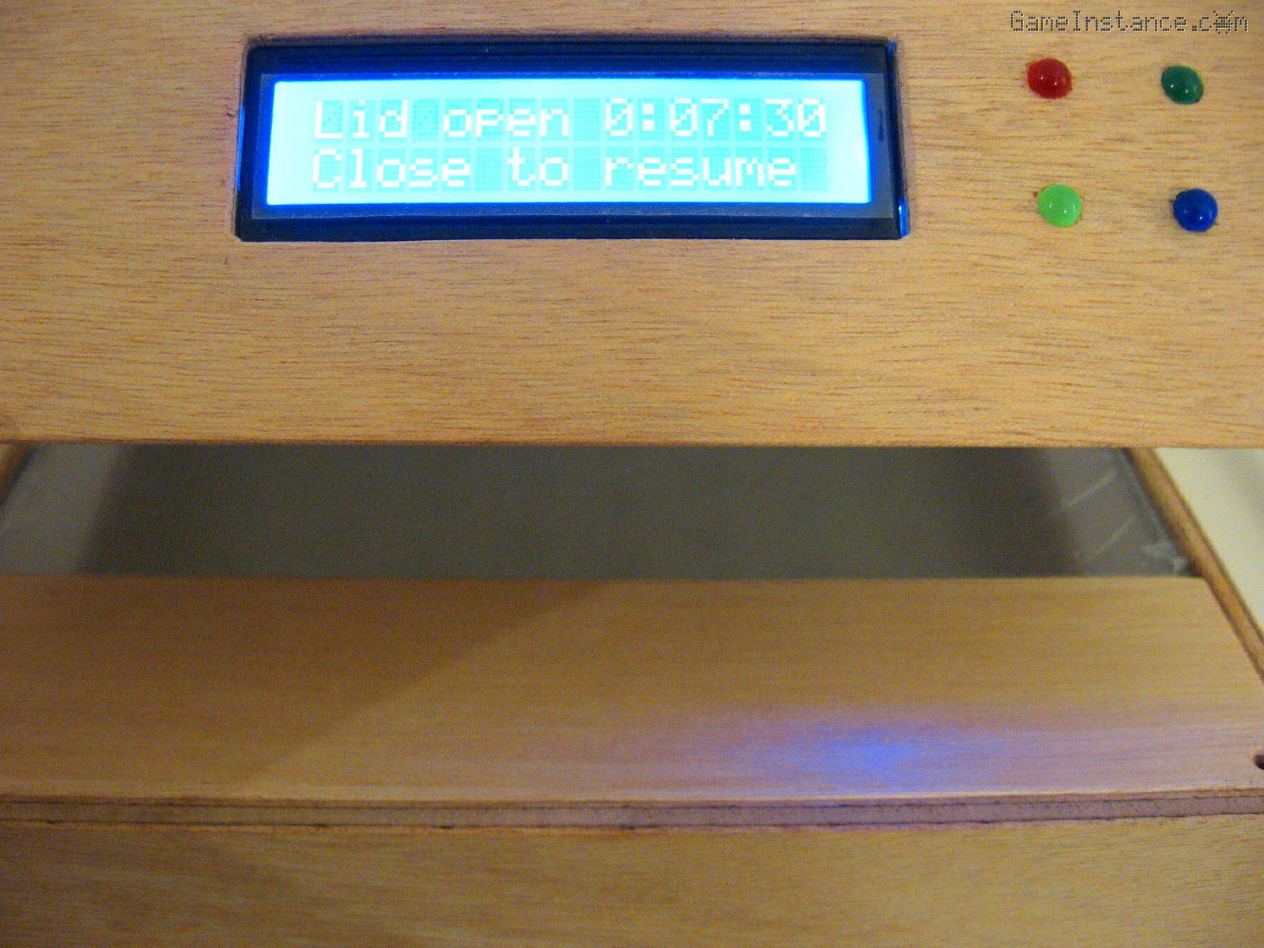
Here's another photo from the front. I've flashed a test sketch to see that all the buttons work and that the lid sensor detects openings and closings. The relay gave me some headaches because it didn't open the LED circuit. It was making a faint sound like it tries to open but it cannot. I feared the contacts inside the relay welded together somehow. Tracing back the problem, I found that the output pin was generating 3.3 V instead of 5 V for the HIGH level and that prevented the complete opening of the bipolar transistor. Apparently, simply declaring the relay control pin as an OUTPUT solved the problem.
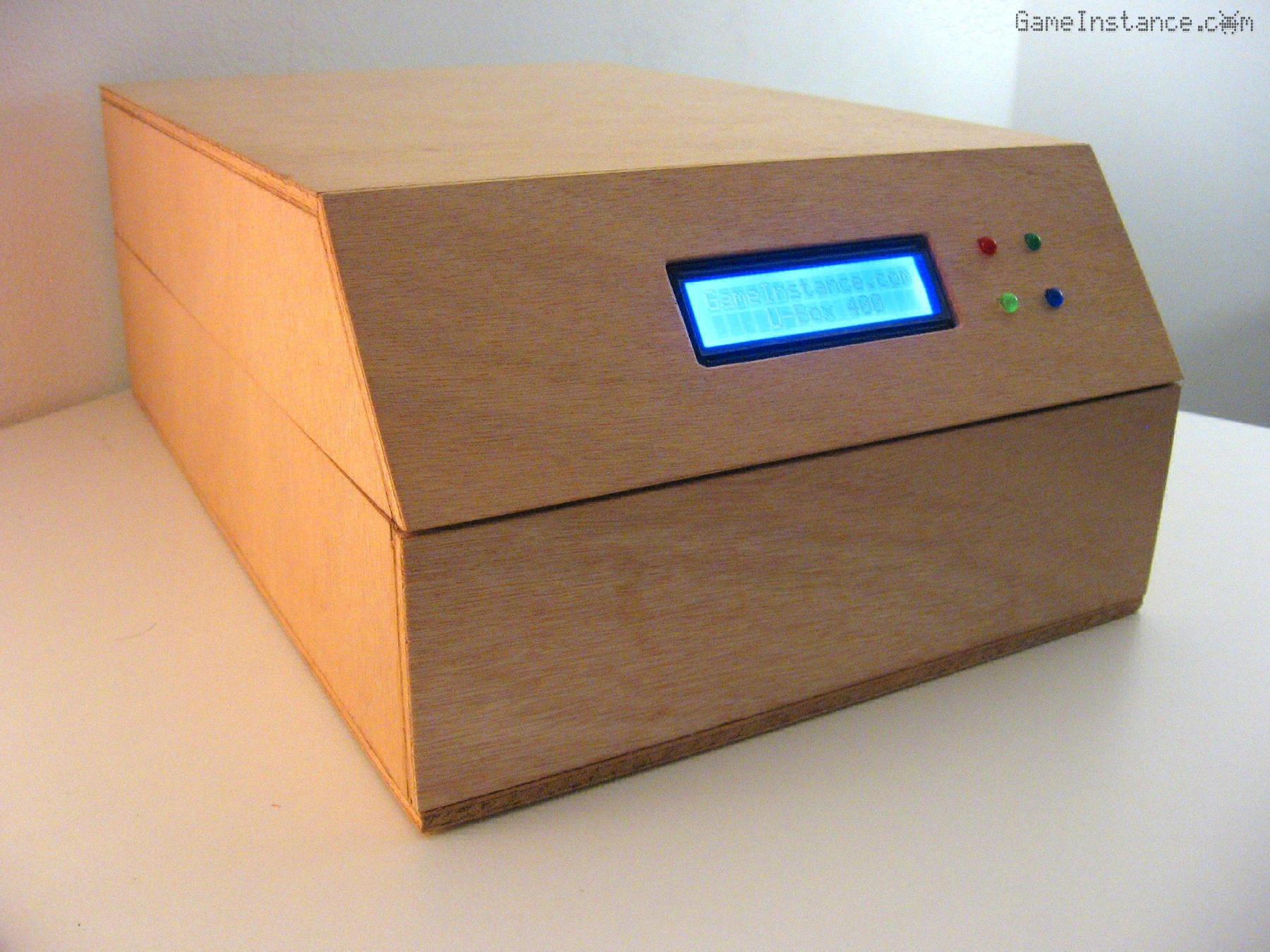
Photo taken while testing the final Arduino code. The lid opening is detected properly and even if the box doesn't close perfectly.
Milestone 4
marks the completion of the box build. In the next post I'll be detailing the Arduino circuit and the sketch that goes with it. In some future posts I'll be making tests and measurements to calibrate the exposure time to various purposes: etch mask, solder mask, dental tools disinfection, you name it.
Update: Check-out Part 5 - The Arduino circuit and sketch.