It is obvious that whoever had this unit, did not care much for it. It did had at least one maintenance and two repairs, from what I could gather by visually inspecting it but all interventions were made by people with very little time, patience or motivation. The most likely explanation is that it was one in a big fleet of others like it. Now that it is in my possession, things will be a little different.
Removing the front panel
I decided to remove the front panel for two reasons. First, because it endangers the integrity of the board while handling it and second, because it needs a proper cleanup. As mentioned before, removing either of the front or the back pieces is an endeavor. Luckily, the front panel is an easier task: one needs to de-solder the meter wires, the connectors and the power-line fuse. The power switch, the meter rotary switch, the voltage and current potentiometers are screwed on the panel using low-profile nuts and can be removed without electrical disconnection.
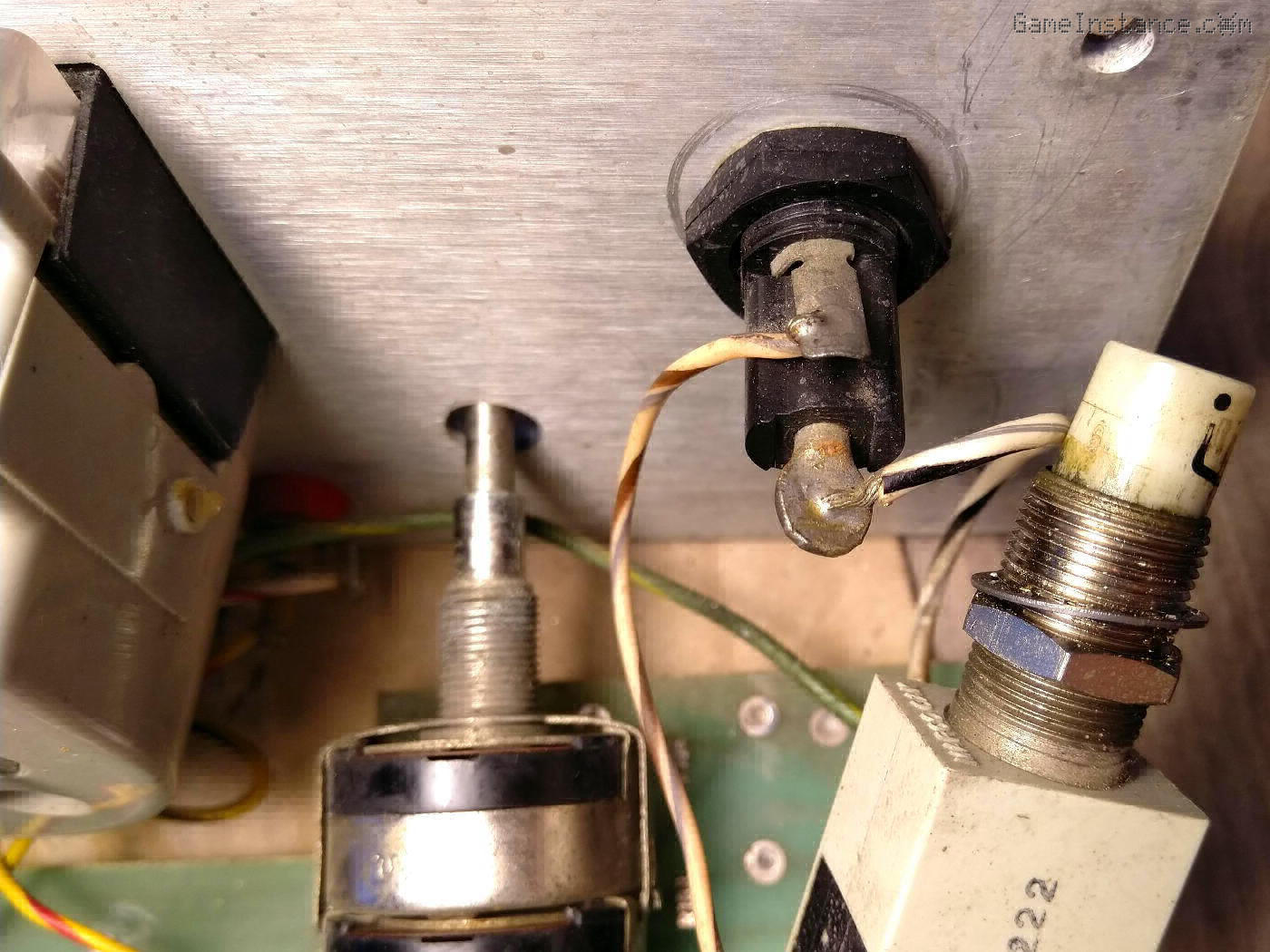 Behind the front panel: the main switch and fuse wiring
There's a third reason for wanting to remove the panel, and that's the inspection of the meter mount. The black plastic bezel is also the supporting piece of the movement and it seems to have a small crack on one side. It's highly likely that it suffered a shock during transport (in Santa's bag, that is). Either way, I'll need to address that at some point.
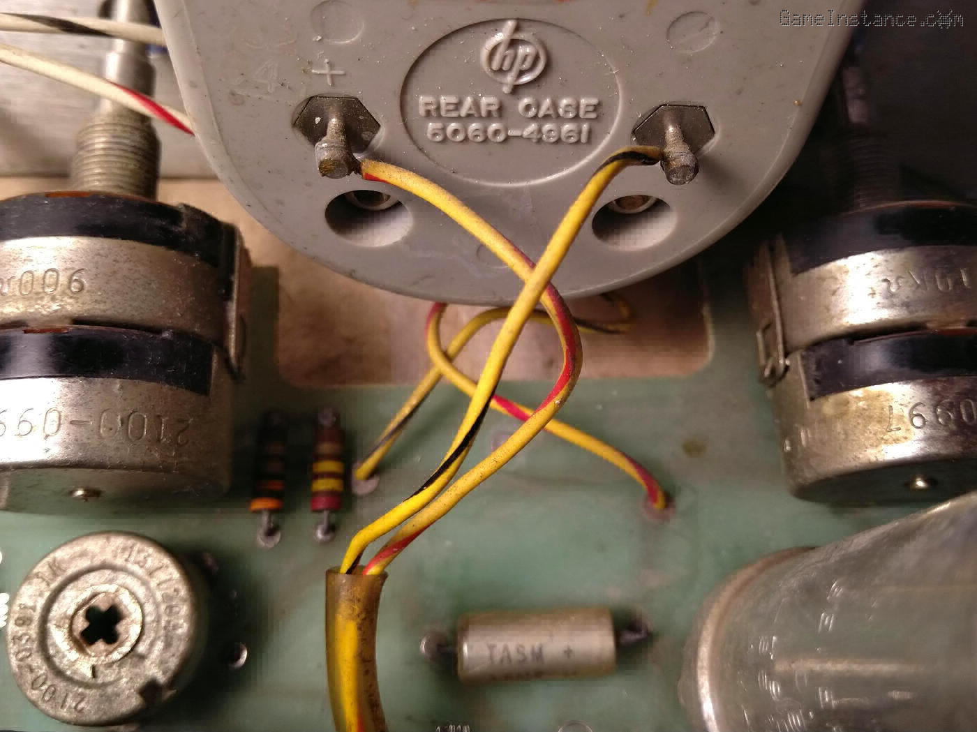 Behind the front panel: the meter and output wiring plus the two stacked potentiometers on each side
With the panel out of the way, I'll also be able to better clean and treat the switches and the potentiometers. They seem to put some unnatural resistance and make some weird noises while turning them. Normally, that should get better with proper lubrication.
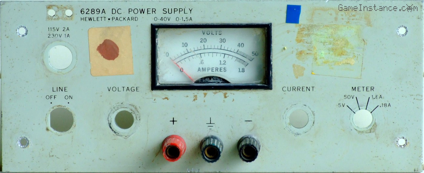 The front panel with its buttons and fuse removed plus a lot of dirt to be cleaned away.
There're quite a lot of pieces that need special attention and the deeper I go into this restoration, the amount of work grows exponentially. I'm going to focus for now on the electronic part. Once that works, I'll handle the rest.
Testing the board
The first thing I did was to check all junctions. Besides some fancy thermally coupled transistor pairs, this power supply has only old-school, bipolar transistors. They all checked fine with drops between 0.5 to 0.7 volts. Neither of the transistors were shorted (a common failure mode) or open and none presented signs of mechanical damage. The diodes turned well also, with forward drops as low as 0.3 V for rectifiers and around 0.8 V for Zeners. All very encouraging signs.
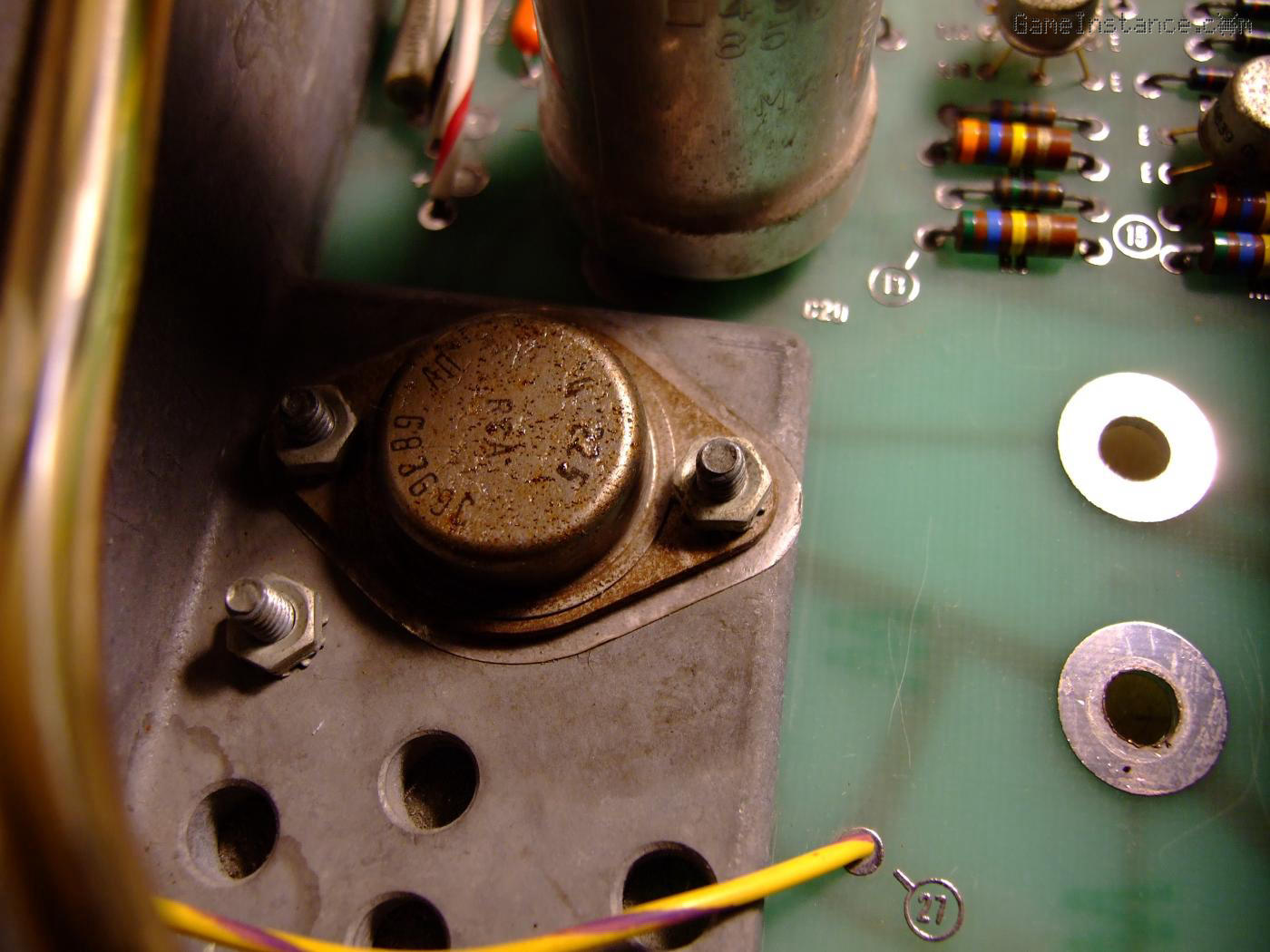 The board with one of its power transistors and the main capacitor mounting holes
Then I investigated the electolytic capacitors to see that none have bulges or leaks. I removed the main electrolytic capacitor because something intrigued me about it and I could not see it properly due to its proximity to the transformer. By the way, it was screwed onto the board so it wasn't much of a job.
How can a 1971 electrolytic capacitor still look that good?
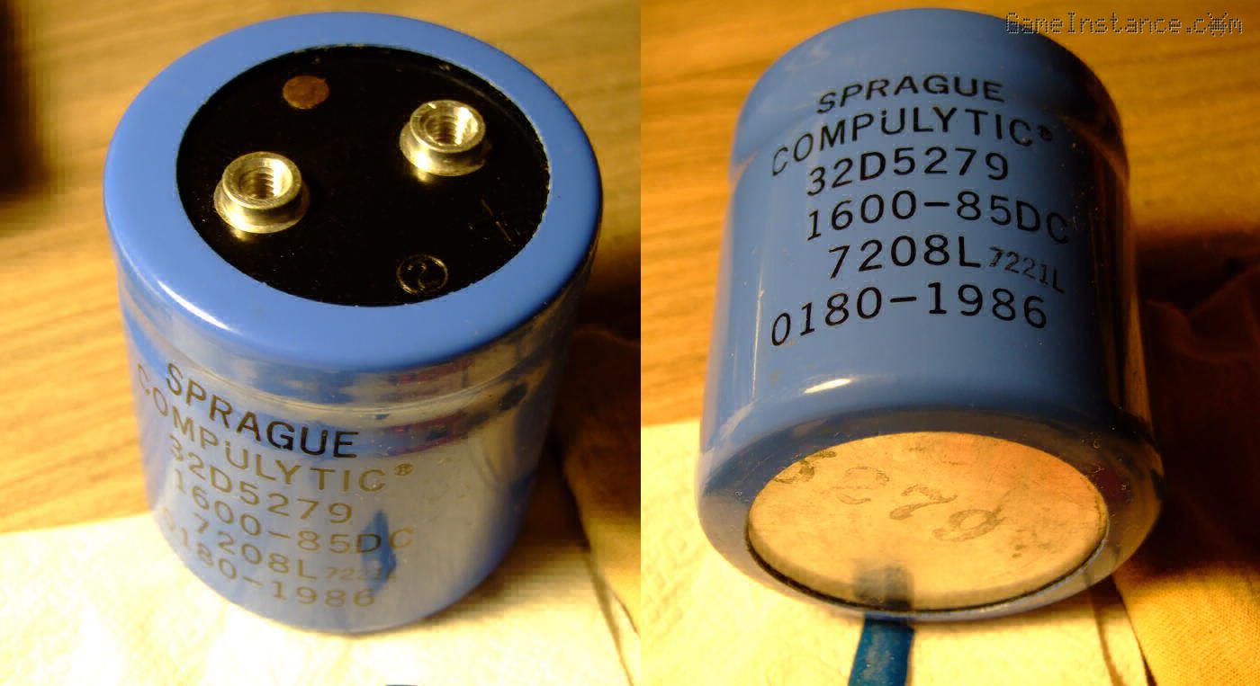 A 30 years old Sprague electrolytic capacitor with a safety pressure release valve.
Well, turns out the cap in question was replaced in 1986, or soon after, but still that's more than 30 years ago, so the question remains. It can be that the unit failed afterwards and after an attempted repair, was marked and shelved, then started accumulating dust. That means the cap has functioned only a small number of hours, hence its exceptional preservation. It is marked to have 1600 uF at 85V and it still measures fine. At 1564 uF, it's well within tolerance.
Again, that's good news because seemingly the production for these caps has stopped and that's because the Sprague company doesn't seem to exist anymore. Globalization must've had its way with it. That's not the end of the world, though, as capacitors with equivalent specs for even higher voltages do exist and they're smaller than the original.
Ready for power test
Before anything, I had to make sure the unit is wired for 230 V. It is stated on the front panel that it supports 115 V and 230 V but one has to hard-adjust that. It turns out the two transformer primary windings were connected in series, indicating the 230 V configuration in accordance with the datasheet. Apparently the supply came pre-wired for 115 V operation and that, at a later moment, it was converted to 230 V. Another brutal intervention can be seen on the PCB as the technician used a cutting tool to cut-isolate and peel sections of it and then soldered a piece of wire to serialize the windings. The cutting tool slipped to scratch other traces as well. This, again, shows that this device was part of a herd, and manipulated as such.
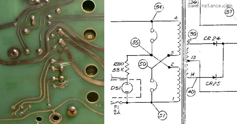 HP 6289A board showing the transformer wiring for 230 V. The schematic represents the US power configuration.
With the board clean of dust and objects that may cause shorts, uninterrupted traces, functional transistors and diodes, all capacitors in apparent order, without any physical damage to the rest of components, I was ready to power it. I've hooked my trusty DMM on the output, on a safe 200V DC range and adjusted the coarse voltage potentiometer to 1/4 of its scale. I replaced the power cable which was rather too long, thick and had a weird plug terminator. All is now ready for the power test.
To be continued.