Didn't go fizz, puff and more importantly, it didn't boom either. Aside the warm hum of the transformer, powering it was totally uneventful. Nothing heated up excessively or out-gassed after 5 minutes of overly cautious observation.
In case you don't know what I'm on about, do check the Disassembly and investigations and the Restoration of an HP 6289A first.
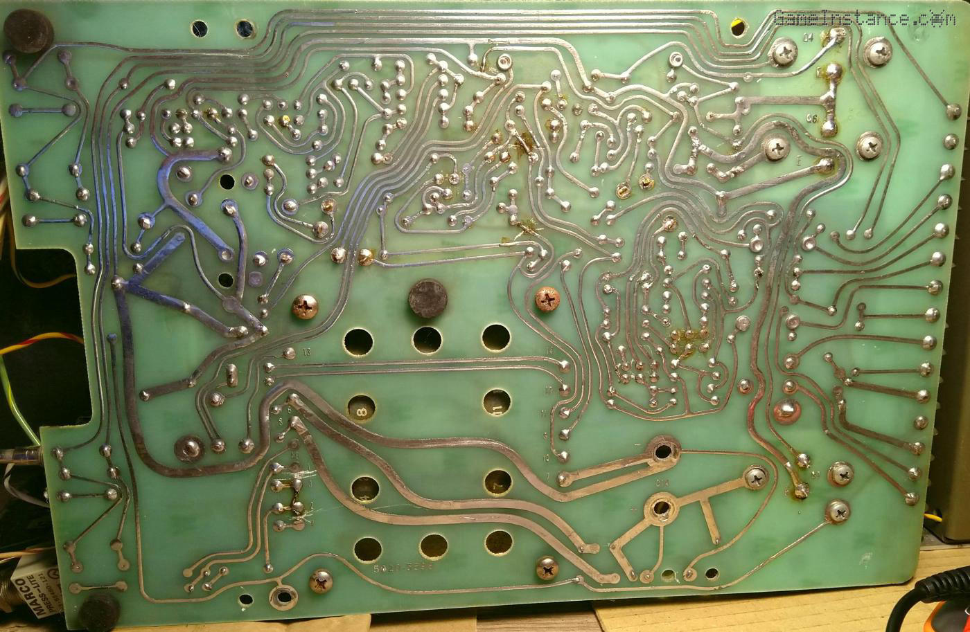 HP 6289A: the back of the board revealing some of the previous interventions
The output of the power supply was way off. It was supposed to deliver 40 V by design, with the probability to do a maximum of 50 V, according to its movement. Instead the output was 60+ volts no matter the voltage potentiometer was set on. On the bright side, that's an indication that the transformer still functions. I feared it may not, given its state.
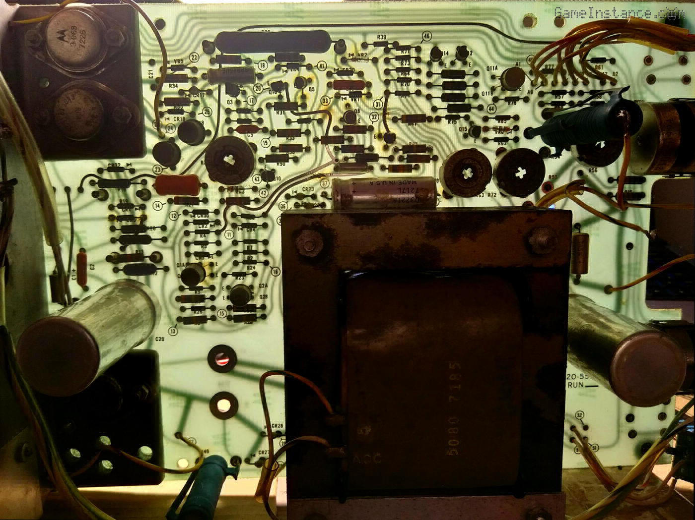 HP 6289A: a see-through view of the board's front-side, showing the parts, the top and bottom traces
With the power off, I checked again all junctions to see that nothing broke after the power test but I did observe something off. I didn't notice it before, probably overwhelmed by so many new and old things. The Zeners were all supposed to have a forward drop around 0.8 V and to have a particular glass package with a red polarity mark. One did not, namely the one labeled VR1. Here's a closer look on that PCB region:
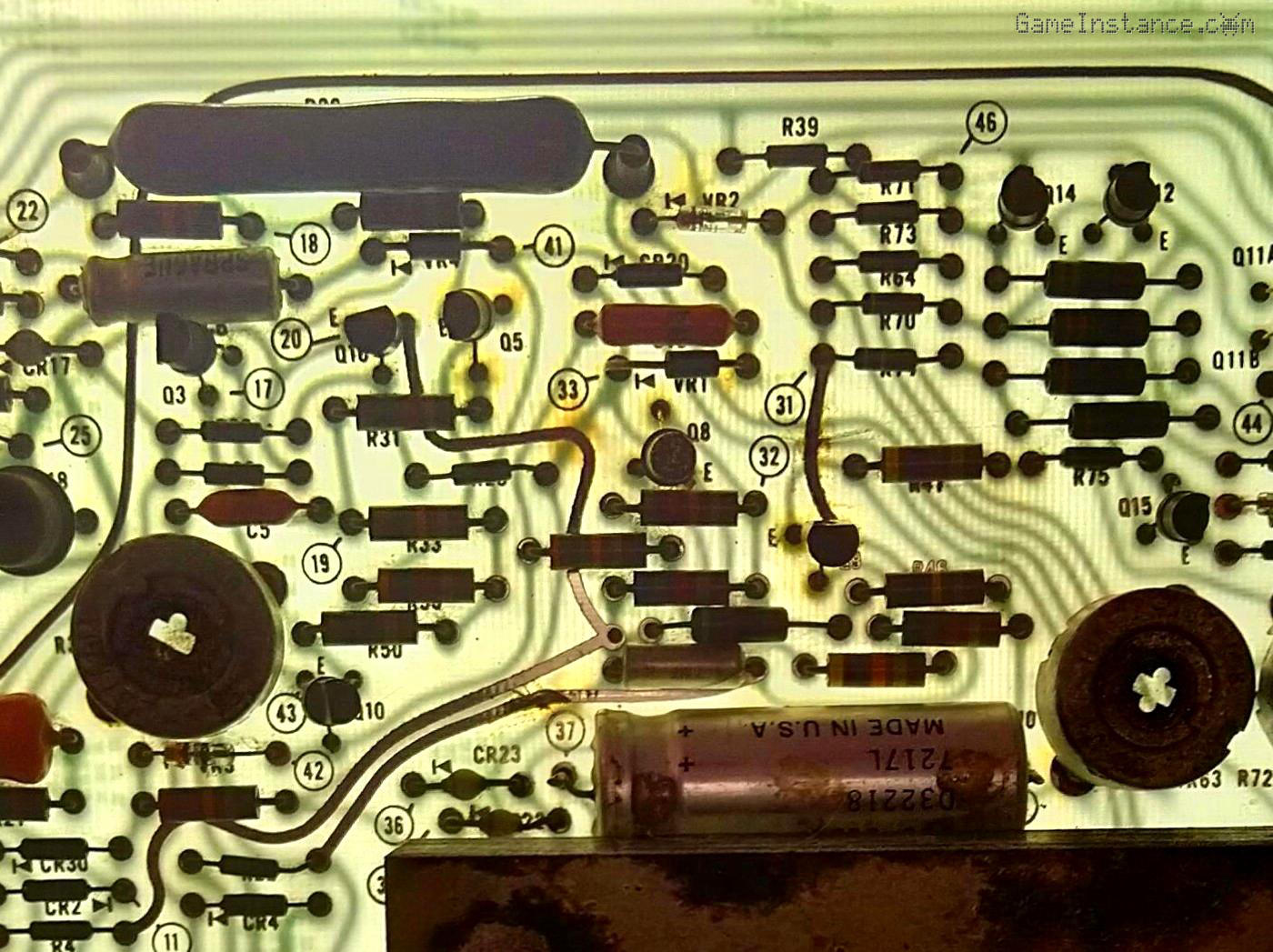 HP 6289A: a zoom into the reference regulator region. VR1 doesn't look right.
According with the datasheet the VR1 and VR2 were supposed to be 6.2 V Zener diodes of the same type and they're clearly not. I went ahead and carefully de-soldered it from the PCB. It turned out that it was a normal rectifier diode of the 1N400x family, far from what it was supposed to be. I was lucky to have Zeners with similar specification already and put one in its place.
I powered it back and, surprise, it worked! It was giving out a controlled voltage and even the current potentiometer was doing its thing. I could not believe it so I kept it connected to a power resistor drawing 0.8 A at 8 V for about 10 minutes until the resistor started smelling bad. Needless to say, the WD-40 I used to treat the transformer was beginning to stink too but the important thing was that it's working.
It makes sense now, the VR1 and VR2 are part of the reference regulator circuit that feeds the difference amplifiers for both the voltage and current regulation circuits. With a normal diode instead of a Zener, with no control on its reverse voltage, there was no regulation on the feedback circuit. No wonder it was outputting around 60 V, there was nothing controlling the power transistors.
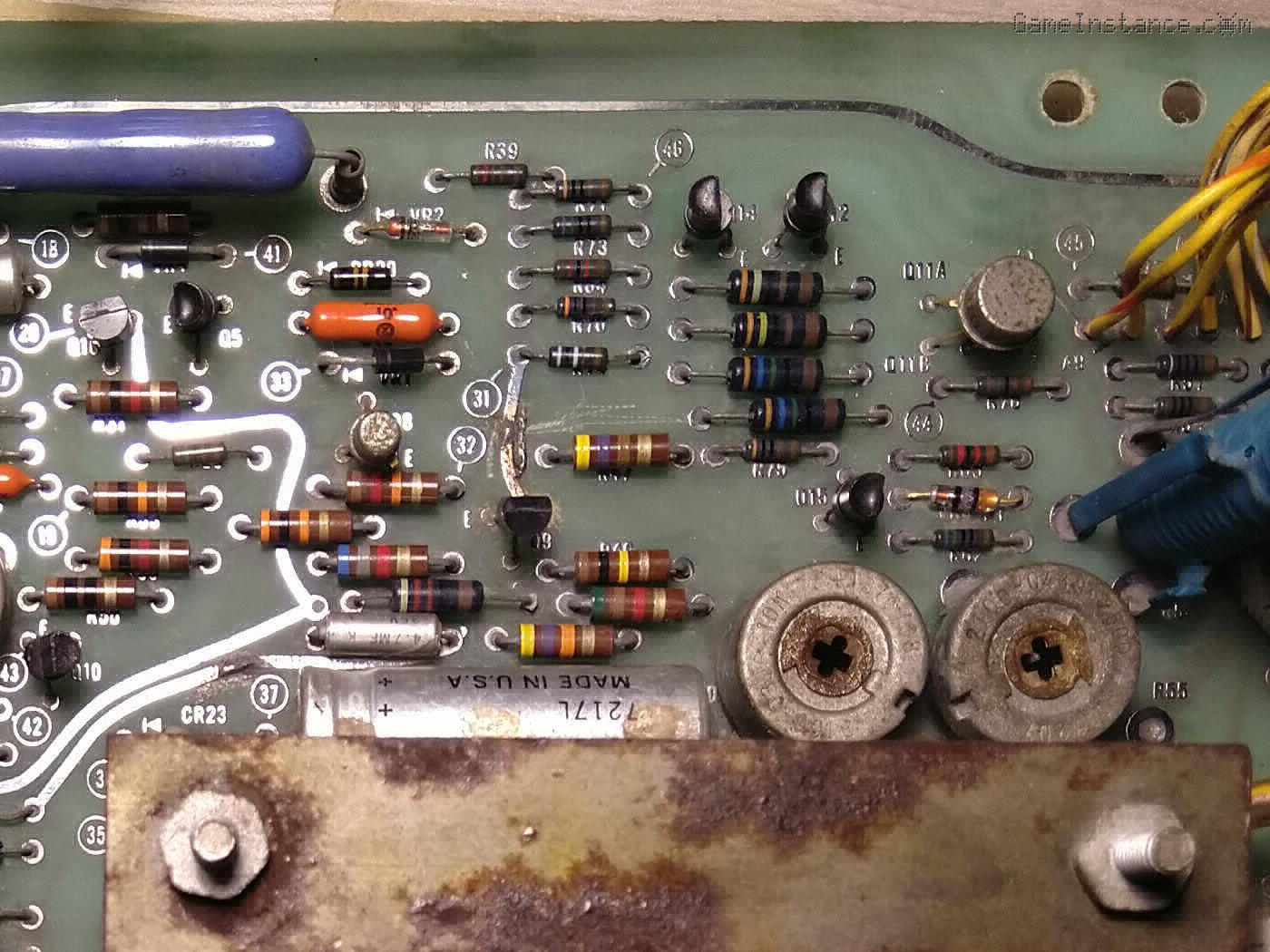 HP 6289A: a zoom into the reference regulator region. Top traces interrupted, likely to isolate sub-circuits.
Looking at it retroactively, I did see that the PCB was scratched in the generic area of the reference regulator, exactly where the VR1 resided. Most likely someone identified the problem well but replaced it with the wrong part. Either this was a screw the datasheet, I know better, hail-mary quick fix or someone with no training or experience tried to do it and, since it didn't work after the said attempt, was marked and retired from action.
With that solved, I can continue with the messy part. Cleaning the panels, the front and the back piece, the buttons and the movement. Heck, that's a lot of careful cleaning. This unit was designed long before today's cleaning solutions, so choosing the right ones won't be as easy and straight-forward as the repair. Nonetheless, it needs to be done.
Stick around for updates.