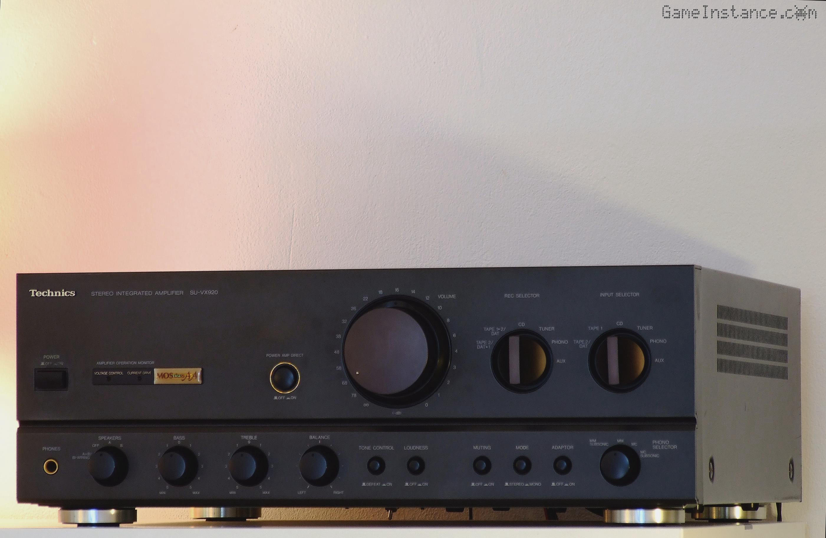
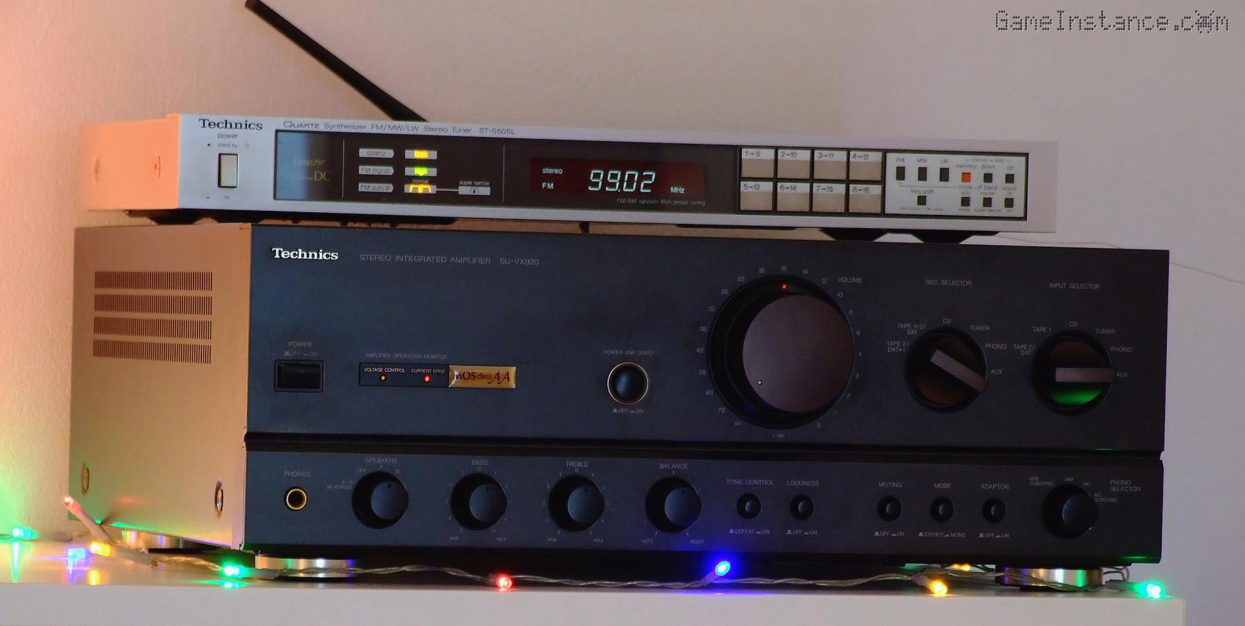
Few months ago I got this SU-VX920 as a defective unit and it was a handful to repair but I learned a lot of tricks from this experience. It was a risk that I took for its rather unique design, namely the MOSFET AA-class pre-amplification stage followed by a massive output drive comprising two pairs of complementary transistors per channel... and it was a rewarding endeavor. As a personal preference, I'd choose field-effect transistors over anything else for their near-infinite gate impedance with superb effect on the sound definition. They have all the good characteristics and none of the drawbacks of triodes. While I'm a fool for VFDs, I simply cannot stand tube amplifiers.

This is a short article containing personal observations, opinions, things I like and hate about the SU-VX920 compared to other, similar amplifiers of its era.
Alternatives
I would start by saying that this design is not unprecedented. The front panel arrangement, the double transformer, the heat-sinkinig piece and the overall component placement are suspiciously similar to an earlier Kenwood model, the KA-7010 or its bigger brother, the KA-7020. Weirdly, I sort of like the KAs for this. Some will appreciate the power capacitor placement closer to where power is needed, namely on the main board, the lower THD rating and a higher dumping factor. Onto more geeky things, the Kenwood service manuals are infinitely better that any of the ones Technics produced during that period and, personally, I like that they color marked the active components. They have solid looking PCB with thicker traces and more copper pour that the Technics. The boards are fully accessible from the technical hatch below the unit, which I cannot say about the SU-VX920 and, oh, I dig the badass black coated, shielded transformers. The circuit of the KA-7010 relies entirely on discrete components, with the exception for the Phono stage and the Tone correction - which can be bypassed - and the protection circuit that has no signal processing function. Even though I've never seen a KA first hand, I already know they are good competitors to Technics and they're significantly cheaper too.
In the same price range, era and following the same design is the Pioneer A-757, yet another nicely crafted Japanese amplifier with even lower THD. It too is twin-transformer but, unlike Technics, the Pioneer ones are actually potted, practically eliminating the grid frequency hum. And I like more the futuristic individual honeycomb heatsink elements per channel than the mono-block one found in the Technics, the black PCB and the seriously cool mechanical shaft connecting the volume button to the potentiometer inside a shielded case protecting the high impedance input circuitry. The nerds of the early 90s must've been drooling all over these.
All in all, the SU-VX920 is not a bad choice. It is in fact the contrary. The front panel is in another class in terms of refinement: the knob quality, the controls disposition equilibrium and even the glyph choice was better. The 90s and onward exterior design was nicer, making all Technics models look modern even today. Getting back to the power capacitor placement, one can argue that the audio spectrum does not have the same power requirements as a digital system and so the parasitic inductance of the wires connecting the power pack to the main PCB is not a tradeoff but actually a dissimulated 1st-order low-pass noise filtering countermeasure. The case has top reinforcement steel pieces and does not rely solely on the lid to give it structure, a thing that I appreciate and haven't seen in most units.
The crappy
I've said it numerous times about the SU-VX920: I hate the PCBs. It has frail boards with weak lamination, making (de)soldering a nerve wracking process. I don't like the fact that the input signal follows a long way around the main PCB to reach the operation PCB behind the front panel for conditioning and pre-amplifying. True, they are routed on the opposite board edge from the noisy components and are paired with signal ground lines, but still. The Pioneer shielding seems overkill, on the other hand, as a THD improvement of 0.004% is unperceivable to any human ear and the complex volume control mechanical joints to achieve that will likely cause more problems than they actually solve. The fact that all models have joined the cost-cutting bandwagon and grouped various functionalities on the main board, it is not something I appreciate. One board containing most sub-modules is cheaper to manufacture but more difficult to troubleshoot. But hey, that's not their problem once the unit rolls out of the factory gates.
The smart
The unappreciative eye, such as mine from two months ago, would not see it but this design is quite clever and Technics probably obtained the most out of it. If we're to look at the position of the AN7062 we'd realize that it is actually shielded by the massive aluminum heatsink block and behind the all-metal front panel. The two signal ribbons interconnecting the boards are actually separated: one for the high and one for the low impedance ones. Each signal, be it on a ribbon or a PCB, is actually paired with ground lines for noise immunity. The result: a pure and neutral sounding integrated amplifier. The output is cleaner still when using it in DIRECT AMP mode, thus bypassing tone control and balance - my favorite.
Enough with the praise for a 35 years old unit, you'd say, and you'd be right but you don't get to see such wizardry every day, especially not in the more recent devices.

Next up, I'll be looking for a tuner matching the color and style of the SU-VX920 and, who knows, maybe also a decent CD player. For the moment, I've hooked it on DIRECT to the FLAC player combo I built last year inside a silver Technics ST-S505.