By now the audiophile in you will agree that the 8 bit PWM audio isn't a prize. Besides, eliminating undesired components from the low resolution pulse width modulation spectrum is a pain for the passive first order low-pass filter and the phase response of higher order filters make it impractical for quality audio reproduction. Although a sine wave has enough energy concentrated in a single frequency spot to achieve high SNR values, something as diverse as the audio signal simply hasn't. All is not lost though for the ATmega328. Combining more than just one PWM output for audio generation has clear advantages but this article is not about that.
The pivot
Let's plow ahead with the idea of an independent device needing real-time data - to be processed or replayed - in the lines of ATmega328 Audio Controller. High transfer speeds can be achieved by the use of SPI transactions. Being natively equipped with SPI, both the ATmega328 and STM32F103C8 controllers are the subjects of this post.
The parties
The ATmega328, uC2, will be the slave in this tandem for obvious reasons: low memory, low clock frequency, whilst the STM32, uC1, will lead the communication. The ATmega328 consumes data at a constant rate and the STM32 provides it. The trick here is to feed data to uC2 so that it'll never choke or starve.
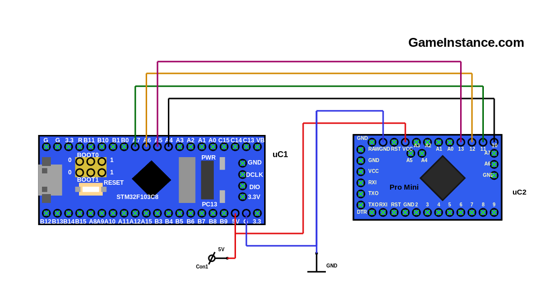 STM32F103C8 and ATmega328 - SPI communication setup
STM32F103C8 ------- ATmega328
PA4 --------------------------- 10
PA5 --------------------------- 13
PA6 --------------------------- 12
PA7 --------------------------- 11
The logic
is based on the assumption that the feed rate is few times bigger than the consumption rate. At 4Mbps the SPI speed is indeed superior to the 64kbps needed for real-time audio replay. One should keep in mind that the SPI speed is referred to as per byte and not as an average speed. As described in the Serial Peripheral Interface article, the SPI byte transfers are paced down to give the slaves enough time to process every received byte. This further reduces the SPI speed by a factor correlated to the complexity of the ISR logic on the slave.
To this effect, the transmission must be limited to short bursts at equal intervals of time. One way to achieve this is by implementing a timing mechanism on the master side. That no longer applies, however, when trying to cover the case of variable rate consumed data of a VBR encoded MP3 for instance. You're left with only one option: slave feedback.
The slave feedback is a permanent response for of each sent byte. As a reminder, the SPI allows a simultaneous exchange between the slave and master, on different physical lines, MISO and MOSI, and on opposite edges of the clock signal. As a limitation, the slave cannot initiate the communication - it is not in charge with the transmission clock signal. To cope with that, the master maintains a permanent exchange with the consumer (the slave). Such an exchange involves an envoy accompanied by a reception. Using control bytes is inefficient. The only fair alternative is to have the master sending consumable data to which the slave should respond with the feedback. To avoid overfilling the slave's buffer the master is left with only one choice: adjusting the transmission pacing time. As a direct effect, the SPI is slowed down just enough to allow data consumption from the slave buffer without actually depleting it.
The feedback information consists of a single byte representing the gap between the read and write indexes. Obviously this means that the buffer size is limited to 256 bytes and for the sake of simplicity it will remain so.
The code
The master STM32F103C8 code uses the Arduino API.
#include <SPI.h>

unsigned char waveData[] = {
  0xff, 0xff, 0xff, 0xff, 0xff, 0xff, 0xff, 0xff, 0xff, 0xff, 0xff, 0xff,
  ...
  0xff, 0xff, 0xff, 0xff, 0xff, 0xff
};
unsigned int waveDataLength = 10446;
SPISettings conf(4000000, MSBFIRST, SPI_MODE0);

void setup() {
  //
  SPI.begin();
  Serial.begin(9600);
}

void loop() {
  //
  SPI.beginTransaction(conf);
  digitalWrite(10, LOW);
  // slave setup time
  delayMicroseconds(10);
  int i = 0;
  byte aheadDiff = 0;
  for (; i < waveDataLength; i ++) {
    // data exchange
    aheadDiff = SPI.transfer(waveData[i]);
    // slave interrupt extra time
    if (aheadDiff > 128) {
      // more for half-full buffer
      delayMicroseconds(175);
    } else {
      // less otherwise
      delayMicroseconds(20);
    }
  }
  digitalWrite(10, HIGH);
  SPI.endTransaction();
  Serial.print("Sent: ");
  Serial.print(i);
  Serial.print(", Diff: ");
  Serial.println(aheadDiff);
  delay(2000);
}
The sketch above omits the audio data. Please check Realtime_SPI_Master.ino on GitHub.
On the slave side, the code is ATmega328 specific.
static const int BUFFER_SIZE = 256;         // bytes
static const long int SAMPLE_DURATION = 125; // microseconds

byte readData[BUFFER_SIZE];
volatile int iw = 0, ir = 0, ow = 0, diff = 0;
unsigned long int tsProbe = 0, tsNow = 0;

ISR (SPI_STC_vect) {
  // read from the data register
  readData[iw ++] = SPDR;
  if (iw >= BUFFER_SIZE) iw = 0;
  diff = (iw > ir) ? iw - ir : BUFFER_SIZE - ir + iw;
  SPDR = diff;
}

void setup() {
  //
  Serial.begin(9600);
  // sets "slave out" as output
  pinMode(MISO, OUTPUT);
  // sets SPI in slave mode
  SPCR |= _BV(SPE);
  // turns on interrupts
  SPCR |= _BV(SPIE);

  // sets pin 3 as PWM output
  DDRD |= (1 << DDD3);
  TCCR2A |= (1 << COM2A1) | (1 << COM2B1);  // non-inverted PWM mode
  TCCR2A |= (1 << WGM22) | (1 << WGM20);    // fast PWM mode
  TCCR2B |= (1 << CS20);                    // no clock frequency reduction
  OCR2A = 255;        // the max count value, giving PWM period
  OCR2B = 0;          // the value to be modulated
}

void loop() {
  //
  if (ir != iw) {
    //
    Serial.print("Read index: ");
    Serial.print(ir);
    Serial.print(", Write index: ");
    Serial.print(iw);
    Serial.print(", Diff: ");
    Serial.println(diff);
    while (ir != iw) {
      //
      tsNow = micros();
      if (tsNow <= SAMPLE_DURATION + tsProbe) {
        //
        continue;
      }
      //
      tsProbe = tsNow;
      OCR2B = readData[ir];
      ir ++;
      if (ir >= BUFFER_SIZE) ir = 0;
    }
    OCR2B = 0;
  }
}
The slave code is also available as Realtime_SPI_Slave_ATmega328.ino on GitHub.
The Wrap-up
SPI communication presents certain peculiarities - such as the master initiated communication or slave set dead times - but can be circumvented. As long as the slave data consuming speed remains inferior to that of the feeder, the real-time goal can be achieved. The ATmega328 as a PWM audio controller was given as an example for SPI real-time communication, not as a HiFi audio-out device.