One of the hardware limitations of the STM32 DSO is the input voltage range, which is limited between Vcc and GND. That can be a challenge when measuring signals with values that can go below the ADC's ground point. Fortunately this problem can be addressed with a voltage offset adjustment using an inexpensive operational amplifier, such as the LM358, and few resistors. This post explains how to achieve that.
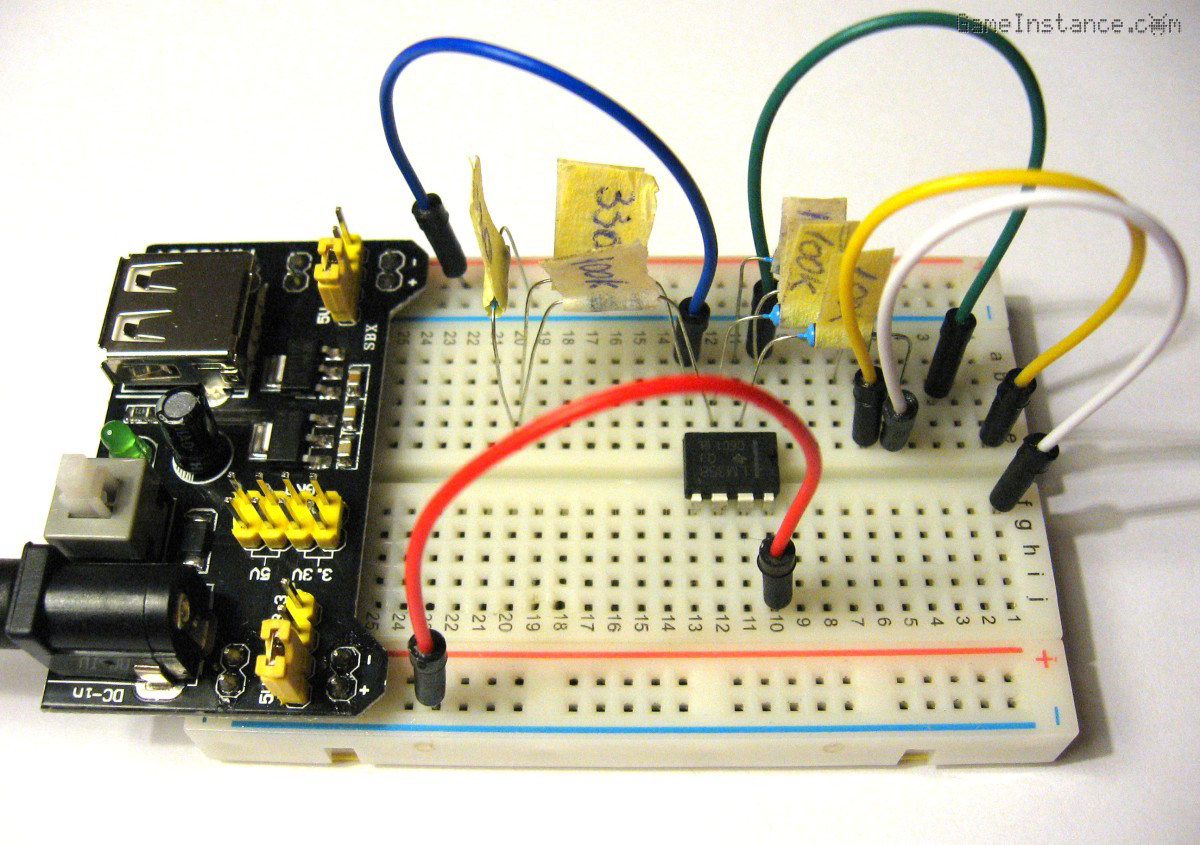 LM358 Op Amp - Offset voltage adjustment breadboard setup
But first
an operational amplifier, as the name suggests, is a purpose-built integrated circuit that amplifies, a lot. Besides the power pins, it has two differential inputs - a positive and a negative - and an output. For most applications that very high gain - around 100000x - needs to be reduced to more stable and usable values. That can be done using a feedback network, meaning that a fraction of the output voltage - the amplified signal - is fed back into the negative input of the amplifier. Some chips are packing more than one such circuit, two in the case of PDIP LM358, thus avoiding the waste of package pins and silicon surface.
A solution
to the problem at hand is suggested at page 14 of the Op Amp Circuit Collection from Texas Instruments. However, I'll be using a simplified version of it, without the potentiometer. Here's the schematic:
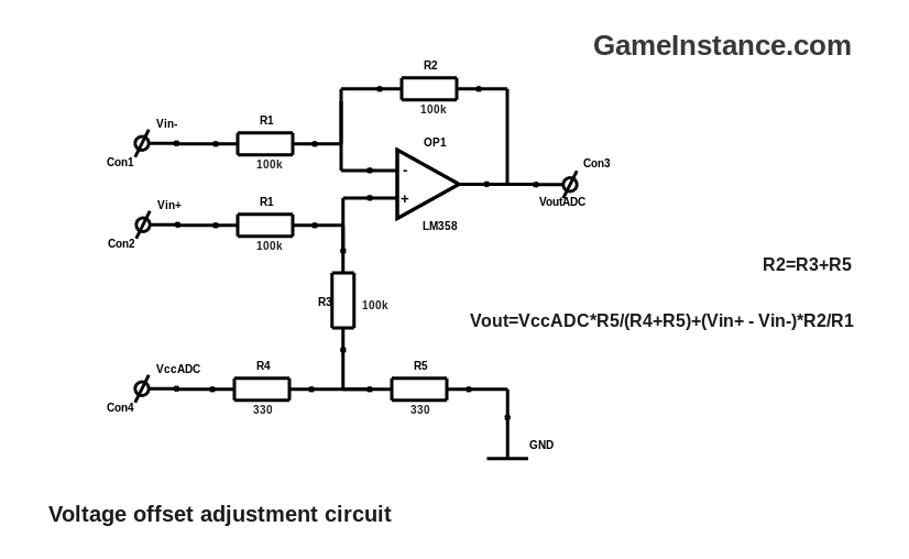
All the feedback network resistors, R1-3 were chosen to be equal in the idea of maintaining an unitary gain. Their relatively high value, 100kOhm, was selected so that the input voltage variations would have as little impact on the offset voltage as possible. The R4, R5 are also equal but their value is low enough, 330Ohm, to keep a steady offset value while limiting the drawn current.
Bill Of Materials:
OP1 - LM358 Low-Power, Dual-Operational Amplifier
R1 - 2x 100 kOhm
R2, 3 - 2x 100 kOhm
R4, 5 - 2x 330 Ohm
Breadboard
Jumper Wires
On paper this should offset the input signal with half the Vcc value. As such, a square signal averaging at 0V and with an amplitude of 1V will be offset with Vcc/2, 1.65V for the STM32. The result signal has a minimum value of 0.65V, well above the ADC's GND point.
The measurements
for Vcc=5V showed the following:
| # | Vin (volts) | Vout (volts) | Voffset (volts) |
|---|---|---|---|
| 1 | 0 | 2.5 | 2.5 |
| 2 | -1.35 | 1.15 | 2.49 |
| 3 | 1.35 | 3.75 | 2.52 |
That means the voltage offsetting goal was achieved at a cost of a distorted output. Unless my voltmeter is wrong, the 3.75 volts for the last measurement should have been 3.85. An error in the offset voltage was recorded as well for the last two measurements. This error could be greatly reduced by replacing all the 100kOhm resistors with 1MOhm ones.
Conclusions
Using an operational amplifier is the way to go when facing the input voltage range limitation some of the MCUs have. Unless it sports a differential input, you have to create one for it. Other than that, measurement equipment need to infer as little influence as possible to the measured signal. The circuit above has an input impedance of at least 200KOhm while voltmeters and oscilloscopes have around 1MOhm. The voltage offset circuit presented solves a big problem but side-effects a smaller one. Solutions do tend to come with trade-offs and the partially distorted output signal is this ones. Going to live with that for now.